Overview
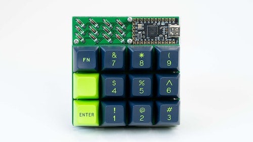
This build guide walks you through how to build the 3x4 Macro Pad by Boardsource from start to finish.
Kit Contents
- 3x4 Ortho Plaid-Style PCB (1)
- FR4 Backplate (1)
- 3x4 FR4 Plate (1)
- Elite-C / Pro Micro (optional) (1)
- Acrylic Cover (1)
- Threaded Standoffs (7)
- M2 Screws (14)
- Diodes (12)
- Hotswap Sockets (optional) (12)
- Rubber Feet (4)
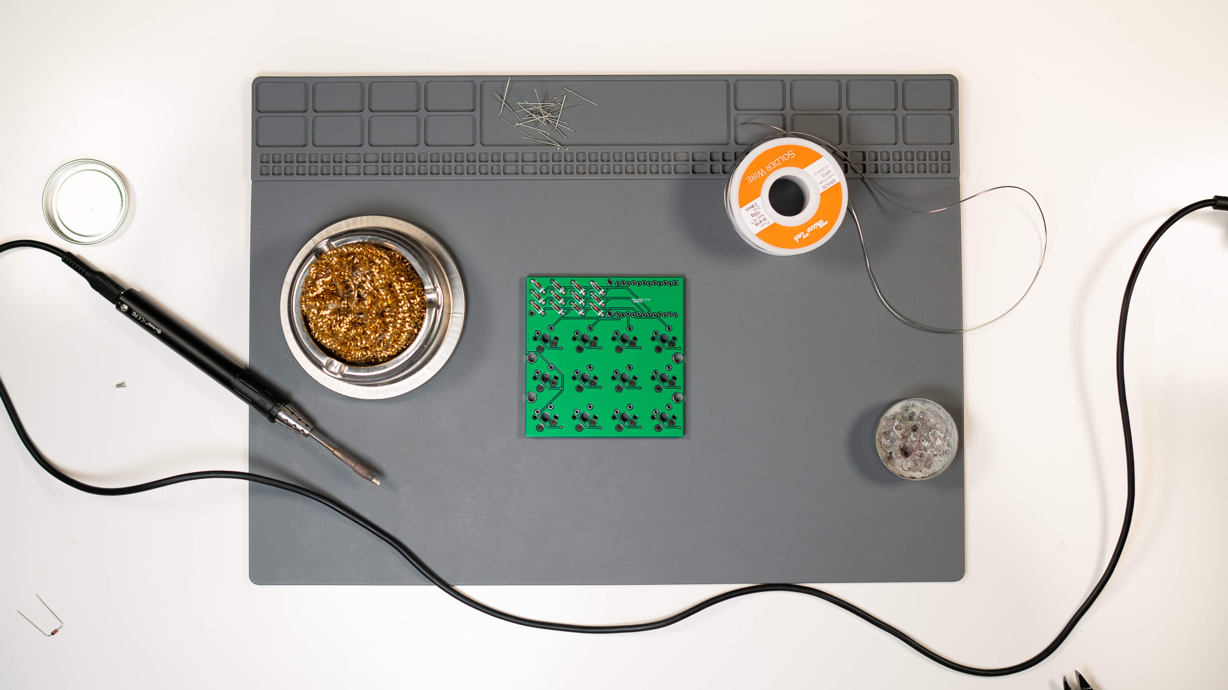
Step 1: Check Kit Contents
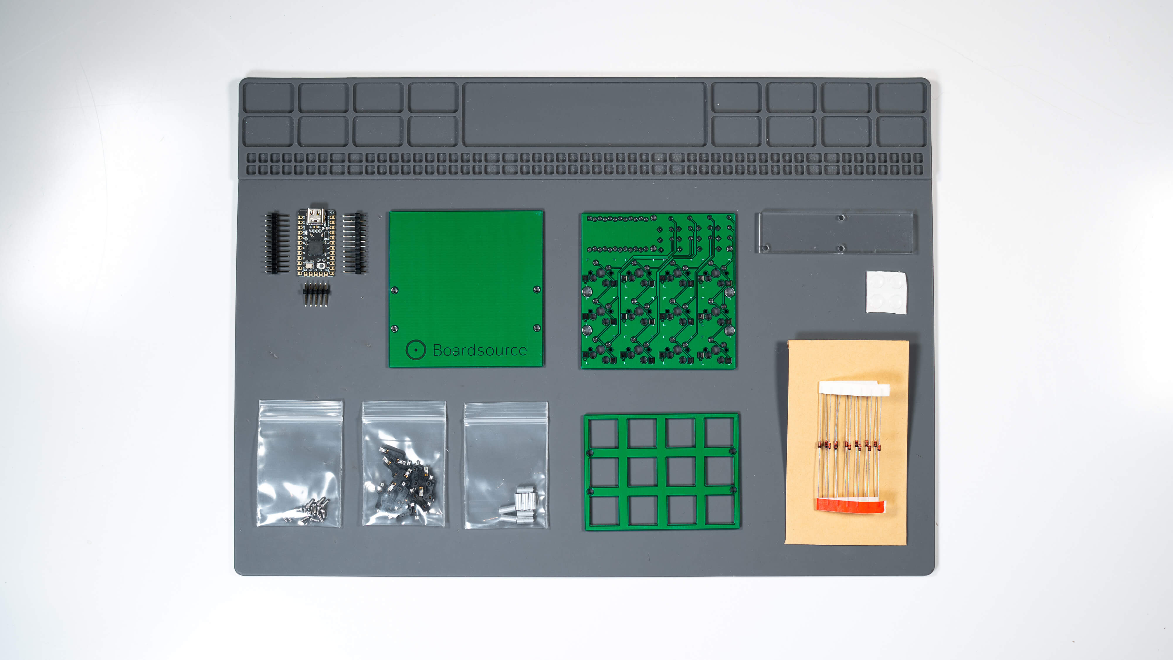
Prior to starting any build it is important to take a look at what you received and what you have in front of you. Not much is more frustrating than getting halfway through a build and realizing you’re missing a single hotswap socket or a screw, or anything for that matter. If you think we forgot to ship something, or if you may have accidentally misplaced something, please reach out to us on Discord in the Help section, or Submit A Ticket in the My Account section of Boardsource.
Note: Boardsource often includes extras of certain items in our kits, it is not unusual to have an extra screw, hotswap socket, or diode. The quantities listed in the Kit Contents section at the beginning of this guide are the true accurate number of components needed to complete the build, if you have more than the listed quantities or have some left over at the end it does not mean that you forgot something or built the kit improperly.
Step 2: Assemble the PCB
PCB Assembly - Prepare Hotswap Sockets
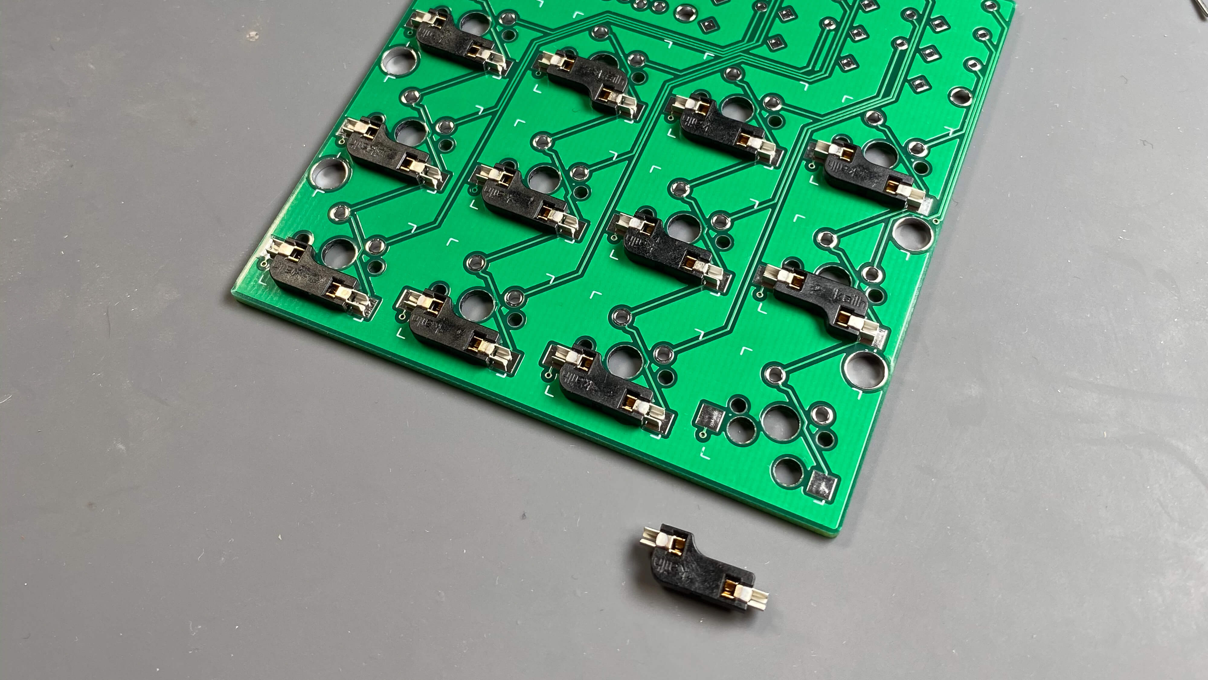
Place each hotswap socket into the designated place on the PCB. Hotswap sockets go on the back of the PCB. The front of the PCB is indicated by the white markings indicating the placement of the diodes, and the back of the PCB is indicated by having solder points for the hotswap sockets.
Match up the solder points to the solder pads on the back of the PCB, you will know that the hotswap socket is oriented properly because no portion of the socket should overlap the hole in-between the pads that allows for a switch post to pass through. If your sockets are oriented improperly they intersect that hole and your switch won’t sit properly. See note below…
I like to place every hotswap socket prior to soldering, and then solder them all at once, but it is your decision on the order of operations there.
Note: I realize this is ridiculous considering this is a build guide, but two of the hotswap sockets in the photos shown are oriented incorrectly, they are upside down. I was very tired when doing this build and I wasn’t used to doing it for a camera, but let this be a lesson that it is important to go slowly, take your time, and check your build at every stage and every step. It’s easier to fix an issue immediately when you notice it instead of many steps down the line. In my photos showing hotswap sockets, majority rules, the majority of the hotswap sockets are oriented properly so mimic that and ignore the two outliers. All hotswap sockets should be facing the same direction and oriented the same, unlike the example photos.
PCB Assembly - Solder Hotswap Sockets
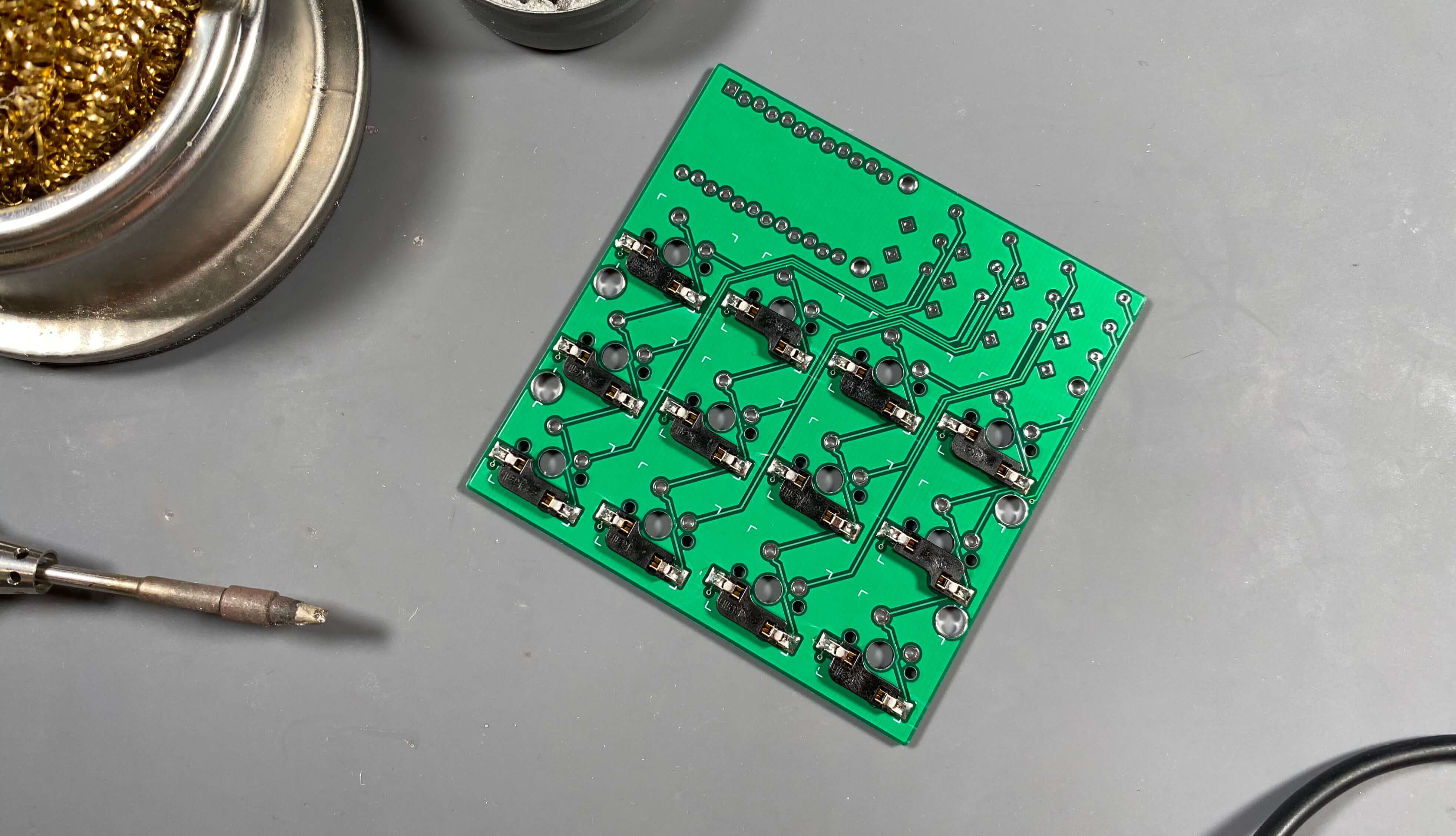 Each hotswap socket needs to be soldered in two locations, one on each side of
the socket next to where each of the switch legs go.
Each hotswap socket needs to be soldered in two locations, one on each side of
the socket next to where each of the switch legs go.
Pro Tip: I like to use a little extra solder when I solder hotswap sockets, don’t go crazy though, just a tiny bit more than you may be inclined to use is enough extra. My logic is that because these take a fair bit of pressure when installing switches, especially if a switch leg is bent, it is easy to put a fair amount of force on the hotswap socket and the extra solder will help to ensure strength.
PCB Assembly - Prepare (Bend) Diodes
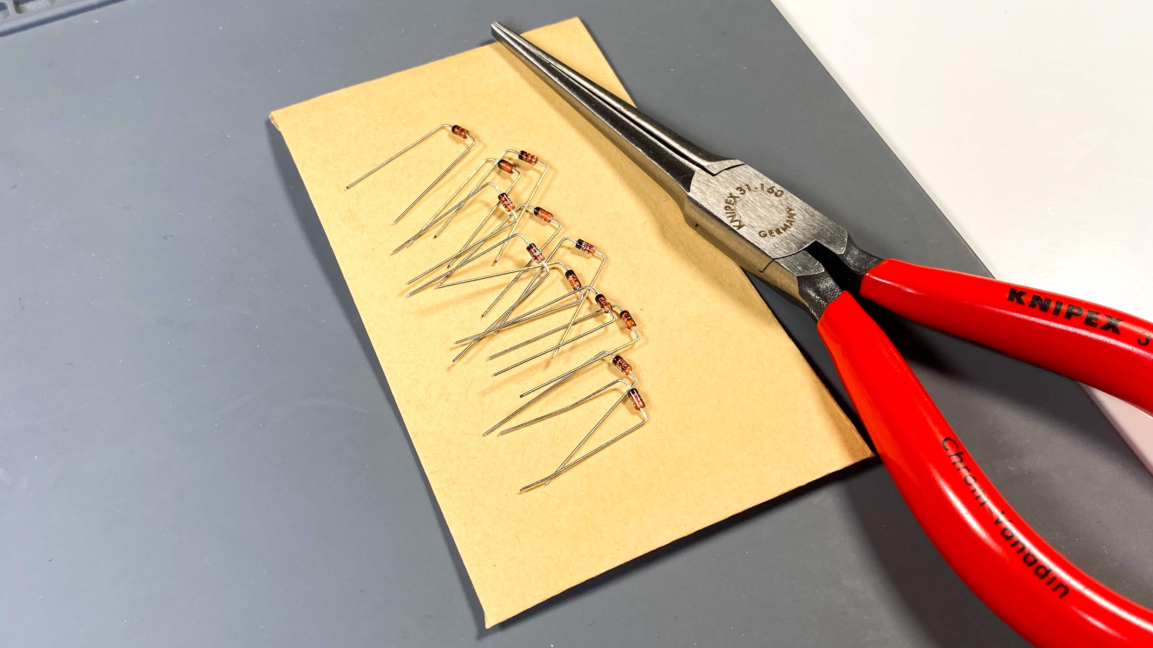
Each diode is shipped “straight" and unbent, or at least relatively unbent compared to how we want them. You must separate each of the diodes from the strip (currently all Boardsource diodes are shipped in a strip) and bend each individually. Depending on the application, I sometimes use a Diode Bender to prep my diodes, but because the 3x4 Macro pad displays the diodes so prominently, I would opt to do it by hand. I feel that bending the diodes by hand allows for more control and less mistakes overall. I always try to bend them each equally so they line up as even as possible on the front of the board. If you don’t take your time to bend the diodes nicely it may not look at uniform on the front of the board. However, some people don’t care about these things as much as me, and no matter how much or little time you spend on this step, the 3x4 Macro Pad will work all the same.
While you’re doing this, notice that one half of the diode glass is indicated by a black stripe.
PCB Assembly - Place Diodes
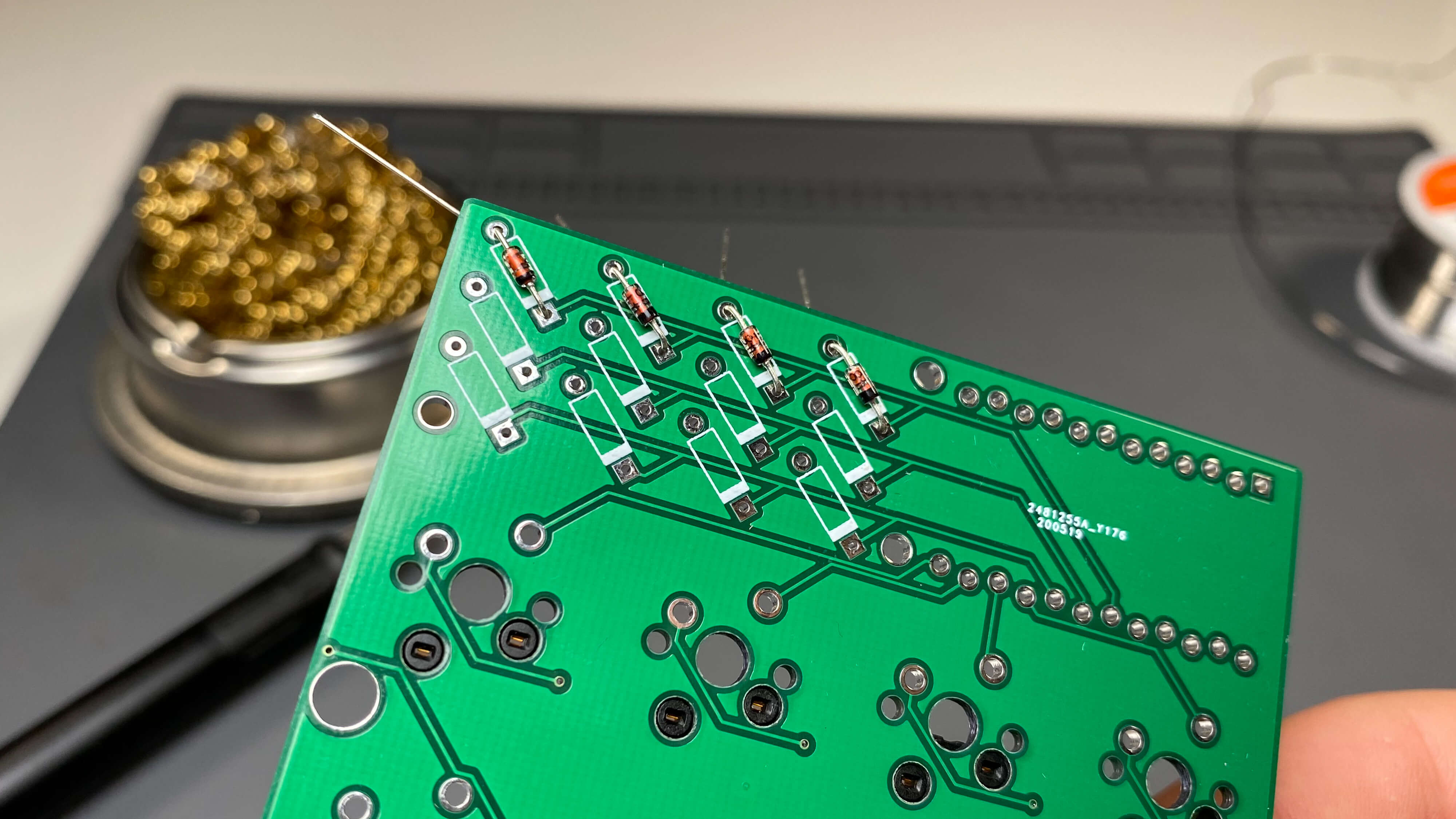
After our diodes are prepared, we can place them into the PCB. The black and orange glass part of the diode goes on to the front of the PCB. You can tell the front of the PCB on the 3x4 Macro in two ways, first, it is the side which has the white (or black if your PCB is white) markings that surround the diode (the glass part) and also because the hotswap sockets go on the back of the PCB.
These markings are created by what is called "solder mask" and this solder mask (white on most PCBs, black on white PCBs) is often used to create pictures, give credit to designers or developers, or anything else really. The solder mask is essentially printing on to the PCB. A very common purpose for solder mask is to give hints about placement of components as well as orientation of components. The 3x4 Macro Pad is a great example of this because the white marking tell us where the diodes go, and also how we orient the diodes.
You will notice that each diode spot, of which there are 12, is outlined with a white box. The white box has a thicker white line on one end (the bottom when the PCB faces the direction of the product photos) and that thicker white line is also on the side of the diode where the leg passes through a square shaped hole, instead of the circular shaped hole on the other side. The shape of hole in a PCB is another way to indicate component orientation. The 3x4 Macro Pad uses two strategies to show which direction the diodes face: the thicker white line on one end of the box made by solder mask, as well as a square shaped hole on that side as opposed to a circular shaped hole.
It is very easy to tell which direction to place the diodes after we know our way around the markings. The glass potion of the diode has a black strip on one end, and the body is mainly orange. The black portion of the diode goes towards the thick portion of the white solder mask and the leg on the black side of the diode glass goes into the square shaped hole.
In short, the black part of the diode glass points towards the square shaped hole.
Pro Tip: Only do a single row/column at a time for the cleanest final product, while applying pressure to the glass part of the diode on the front of the board, bend the legs on the reverse side of the PCB outwards to create tension. This helps to hold the diode in place when you flip the PCB over to solder.
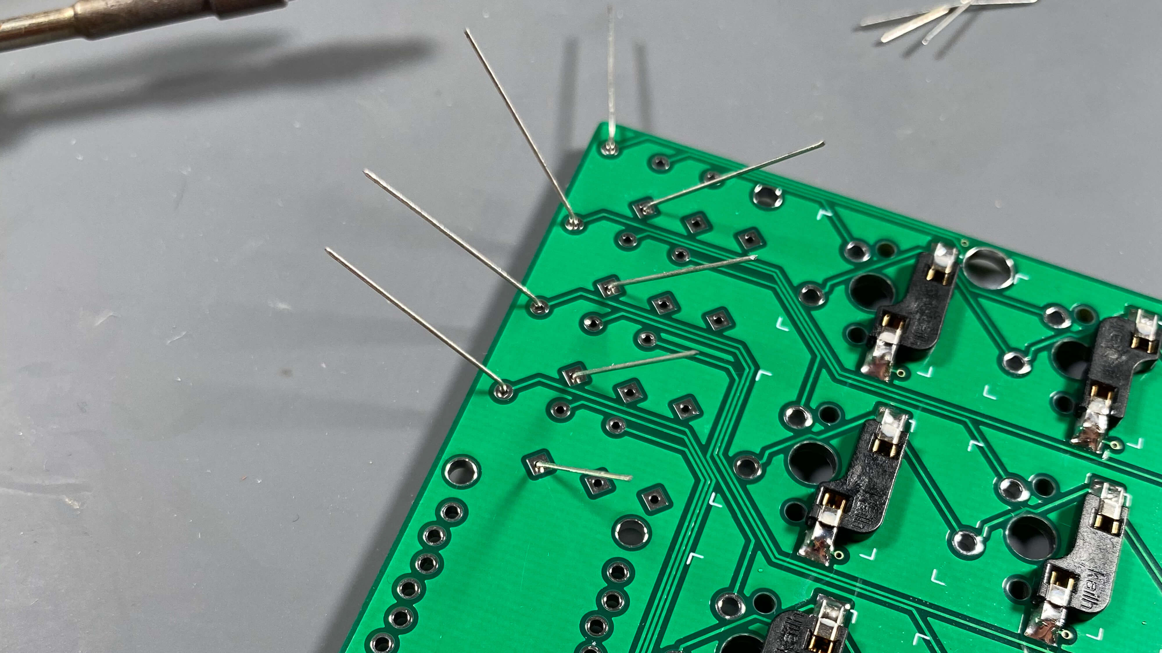
PCB Assembly - Solder Diodes In Place
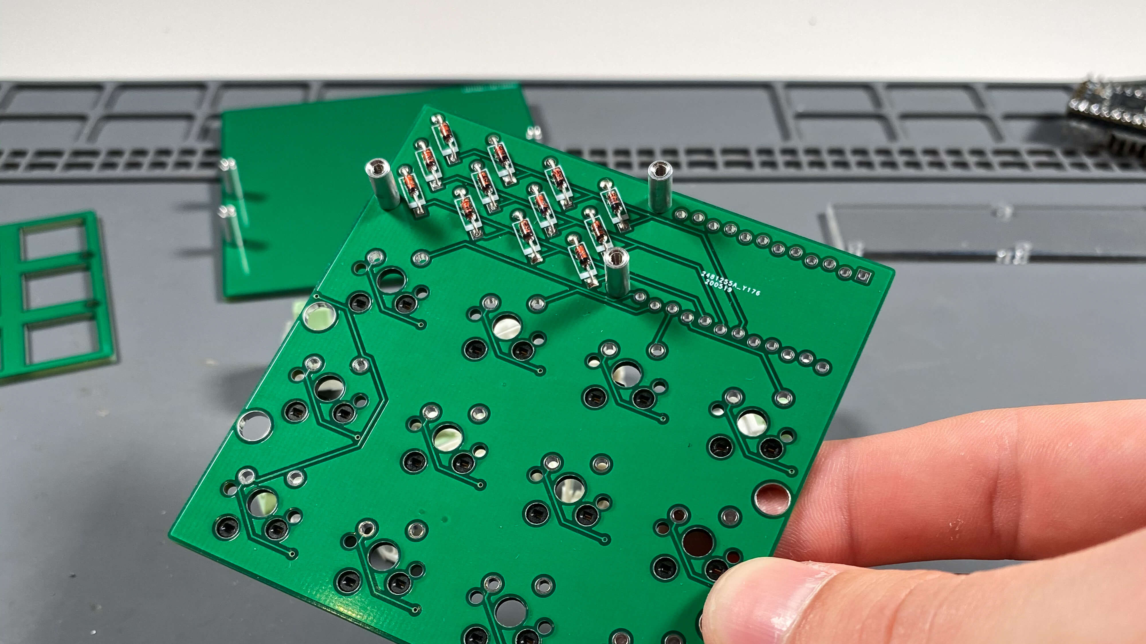
After you have placed all the diodes in the correct position and soldered each of the legs in place, check both sides of the PCB for errors. Carefully check over each of the diodes on the front to ensure that each are oriented correctly, with the black portion of the diode glass facing the square shaped hole, and that each of the legs on the back are soldered in.
Make sure to check each diode very carefully to ensure it is soldered and oriented properly prior to cutting the extra length of the legs off from the back of the PCB. It is easier to fix a mistake before the legs are trimmed.
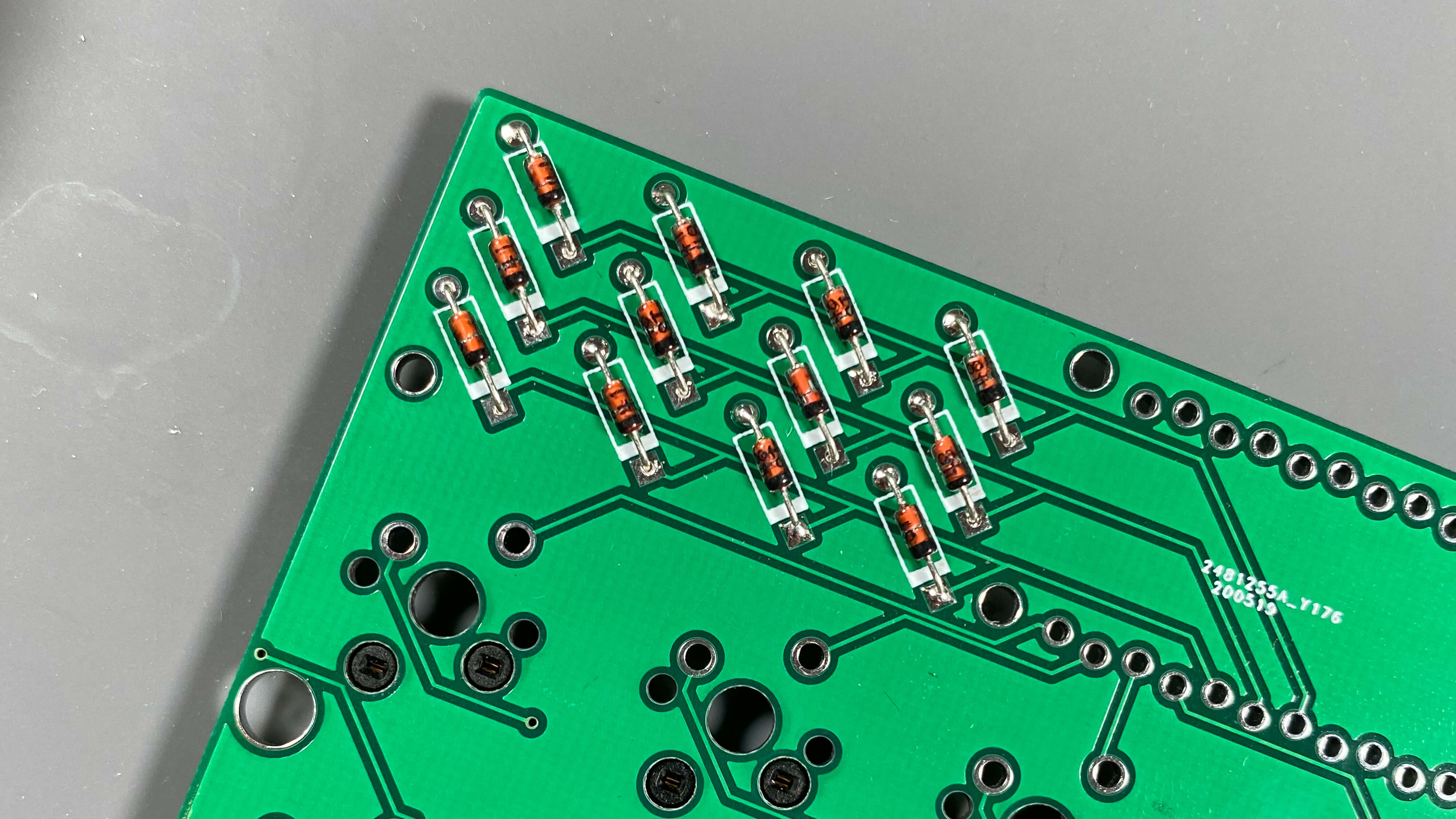
PCB Assembly - Complete
Now that you have installed the hotswap sockets and diodes, the assembly of the PCB is complete for the 3x4 Macro Pad. Make sure to do another review of your work to make sure it is correct before moving on.
Step 3: Prep and Place the Micro Controller
Note: The 3x4 Macro Pad is compatible with either an Elite-C or a Pro Micro, and you are able to purchase either micro controller with your kit from Boardsource. This guide uses an Elite-C but the installation steps are the exact same for a Pro Micro.
Important: If you are using a Pro Micro in your build, flash your keymap to your Pro Micro before doing anything else. Pro Micros do not have an on-board reset switch and neither does the 3x4 Macro Pad, so it will be hard to reset your Pro Micro in order to flash it after it is all assembled. By default, all boardsource_3x4 keymaps come with a Reset mapped. You can activate this by holding down the top left key of your macro pad /while_ plugging it in.
Pro Tip: Prior to moving forward with this guide, you should flash your map to your micro controller no matter the style of micro controller you are using. Like anything, sometimes micro controllers break or are dead on arrival. It is very frustrating to complete a build, assume everything works, and then go to flash your map only to be surprised that the micro controller is broken. It is not a common occurrence at all so don’t be too concerned, I have actually never personally encountered a broken micro controller, but is is best practice to do a test flash prior to using one in your build just to make sure it’s good to go.
Solder Legs to the Micro Controller
In order to use the micro controller on your board, you must first prep the micro controller for installation. This process is essentially the same for every keyboard, you must solder the legs onto the micro controller. Elite-Cs and Pro Micros come with legs in the anti-static baggie. There is usually 3 sets, 2 long and 1 short. We don’t use the short, but we will use the 2 long sections.
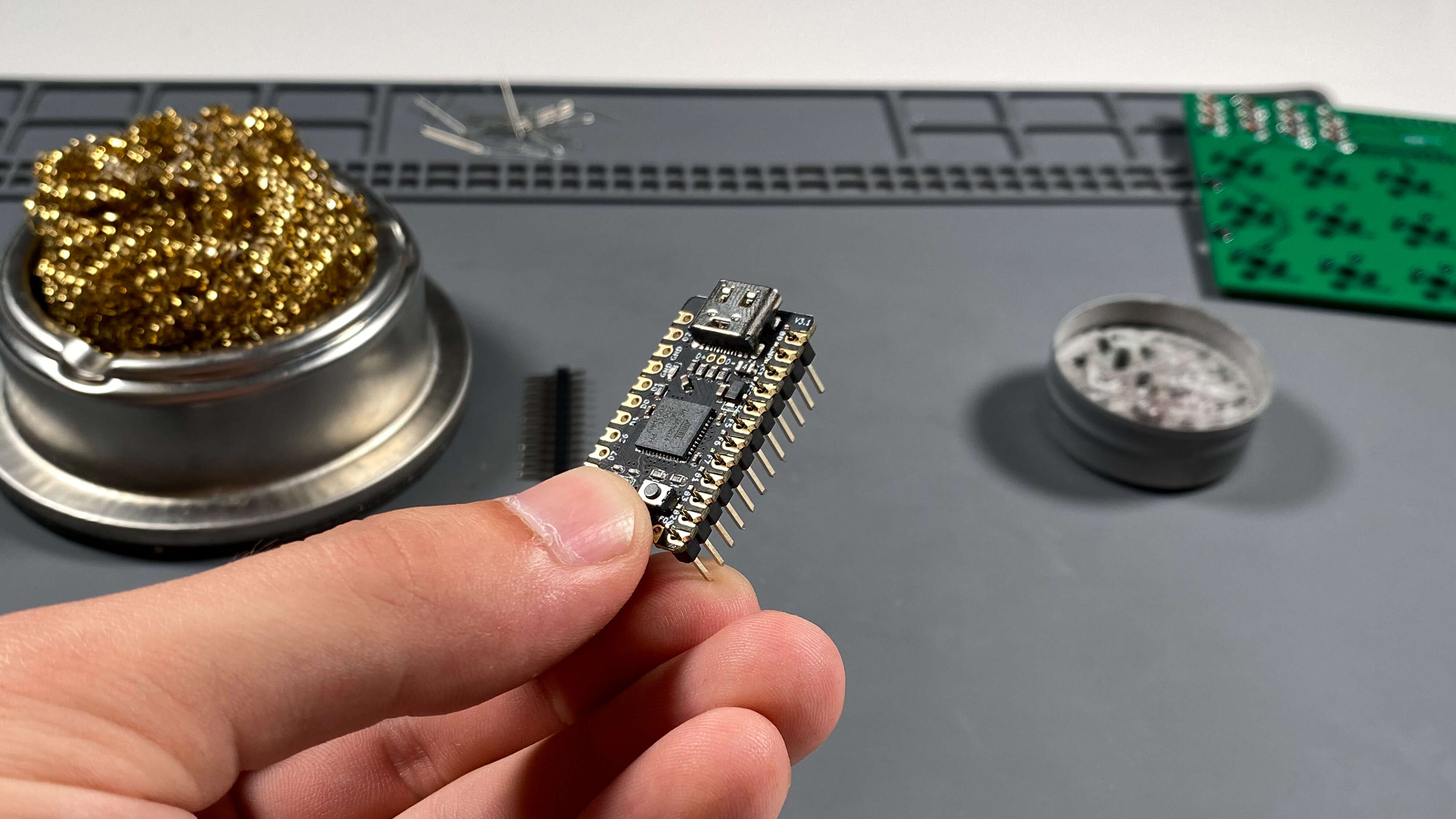
Micro controller leg sections have a black plastic strip connecting them, and that strip is not placed directly in the center of the leg. This placement creates a “short” end and a “long” end. The long end is what goes through the PCB and the short end is what comes up through the micro controller. On the 3x4 Macro Pad the micro controller is installed with the component’s facing up. On the Elite-C this means the reset button is facing upwards. Make sure you solder yours legs in place exactly as shown in the image above, as well as the completed product photos throughout the website. If you install the micro controller upside down, your keymap will not work as you’d expect. Additionally, micro controllers are one of the most annoying things to desolder and fix, so try very hard to get it right the first time.
When soldering the legs to the micro controller, make sure that the legs are at a 90 deg angle to the micro controller and that they are straight the entire length, and inserted all the way. If you don’t take the time to ensure everything is lined up properly and not crooked/diagonal it is likely that you won’t be able to install the micro controller because the legs won’t line up with the holes on the PCB. Again, these are very annoying to desolder and fix so it is important to take your time and try to get it right the first time.
I hold the legs in place, fill my soldering iron with some solder, and then messily “tack” the legs in place in two locations. This basically means I just try to slop some solder onto the legs in two locations to make them stick. It isn’t super pretty, but it is easily cleaned up and can be made to look perfect again. At first you just need to get the legs to stick where you want, then you can move the micro controller, reposition it, and solder the remaining points in a more comfortable way.
Install Micro Controller
Now that our micro controller is prepped and the legs are soldered in place we can install it on to the PCB, which is also done being assembled. The 3x4 Macro Pad uses a zipper-style micro controller connection. Look closely at the holes where the micro controller goes, and you’ll notice they are staggered. This is intentional, and allows you to friction-fit the micro controller on to the PCB. The zipper-style connection is hugely beneficial because it allows you to connect your micro controller without soldering, making it hot swappable without any extra components. Because micro controllers are so difficult to desolder and remove, this is a really great feature. Shoutout to Danny at Keeb.io for originating this idea and making this footprint.
Because the zipper-style connection is a friction-fit connection it can sometimes be difficult to get the micro controller installed the very first time. Do not try to push the entire thing into place all in one go; instead, tilt the controller and start on one side, applying slight pressure and “walking” it in to place. It takes a bit of getting used to but once you do it once it becomes much easier.
Note: If for some reason you hate the idea of the zipper-connection you are of course able to solder the micro controller in place.
Cut Extra Leg Length Off Micro Controller
After mastering the zipper-connection and successfully installing your micro controller, push on the top of the micro controller to ensure that it is firmly seated against the PCB, it should be completely even and only small gaps between the black plastic of the legs and the PCB. Don’t force it but do firmly press it into the PCB.
On the back of the PCB, there is the extra length of the micro controller legs, trim off the extra legs but do NOT trim it completely flush with the PCB. You only need to take off approx. 2mm in order to work properly here, and if you trim it flush with the PCB it may reduce the integrity of the zipper-connection. If we do not trim the legs at all, it will cause the connector of some micro controllers to press against the acrylic cover and raise it slightly, which is not a great look.
Pro Tip: Be careful when cutting these legs down, they are quite rigid and that means when you cut off a small length of them it can go flying. Cover it with your hand when you cut so it flies up into your hand, and not into your eye or across the room for you to step on 20 minutes later.
Micro Controller Install Complete
Now we are done with all the hard parts, and short of any mistakes, you won’t need to use the soldering iron again for the rest of the build.
We have installed hotswap sockets and diodes on to the PCB, and we have prepped and installed our micro controller to the PCB. Let’s move on to final assembly.
Step 4: Final Assembly
Note: Be careful when using the threaded standoffs and M2 screws to not force anything in to place. They are very easy to strip. Do not over tighten.
Connect Standoffs to the Backplate
The first step of final assembly is to connect 4 threaded standoffs to the back plate of the macro pad. This is done by inserting a screw in through the bottom of the backplate and then threading a standoff to the front. Do this for all four lower holes in the backplate.
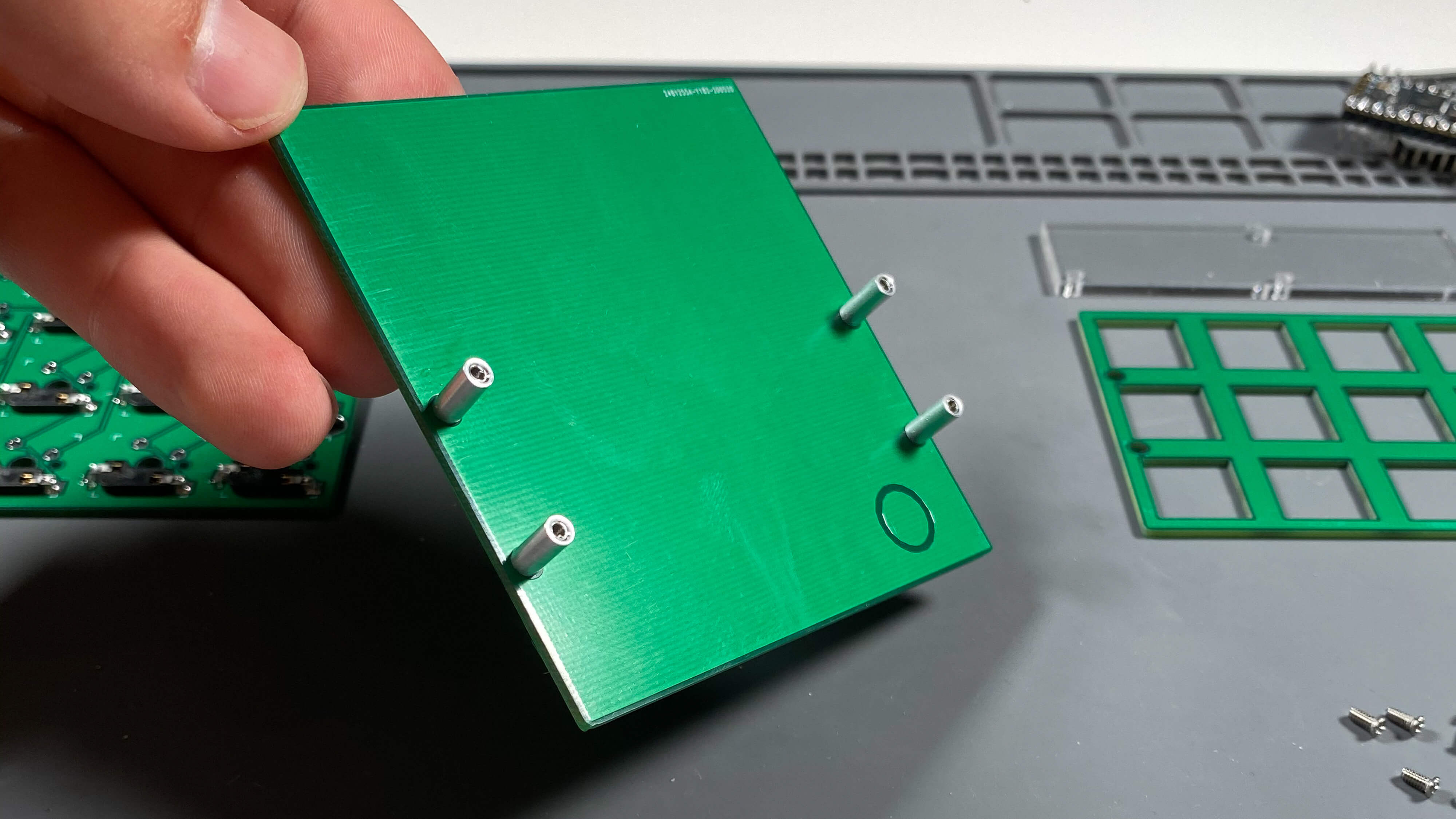
Connect Standoffs for Acrylic to the PCB
Because we won’t be able to access the back of the PCB once we are further along assembly, it is important to install the 3 remaining threaded standoffs to the PCB. These standoffs hold the acrylic cover in place. These standoffs are secured with M2 screws through the back of the PCB using the same method as the backplate.
Install Switches Into Plate
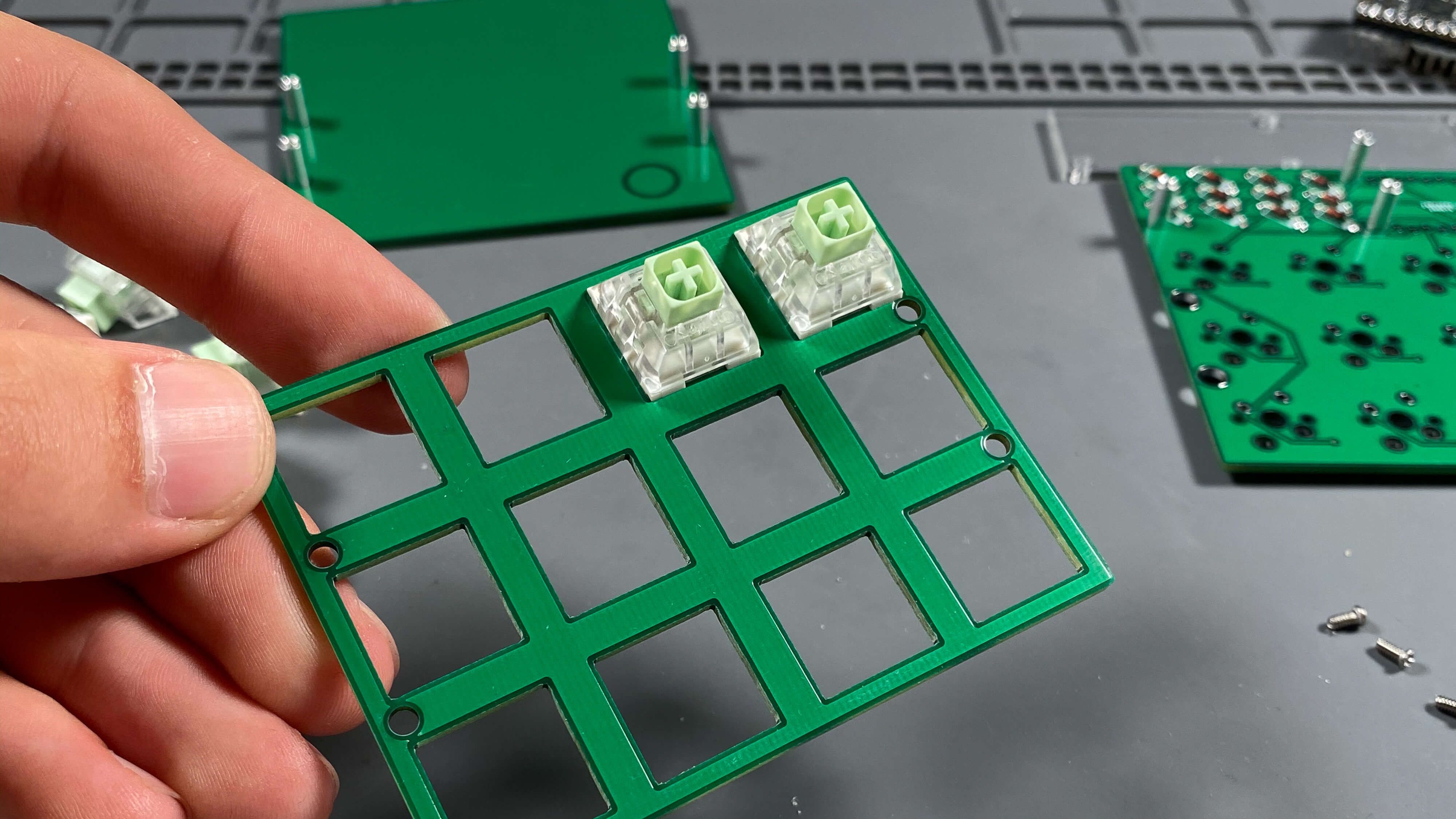
Install a MX Compatible switch into each of the switch holes on the plate. Install each switch so that the switch legs run along the lower side and are ‘down.’ Make sure each switch is installed in the same exact direction.
Sandwich the Plate onto the PCB

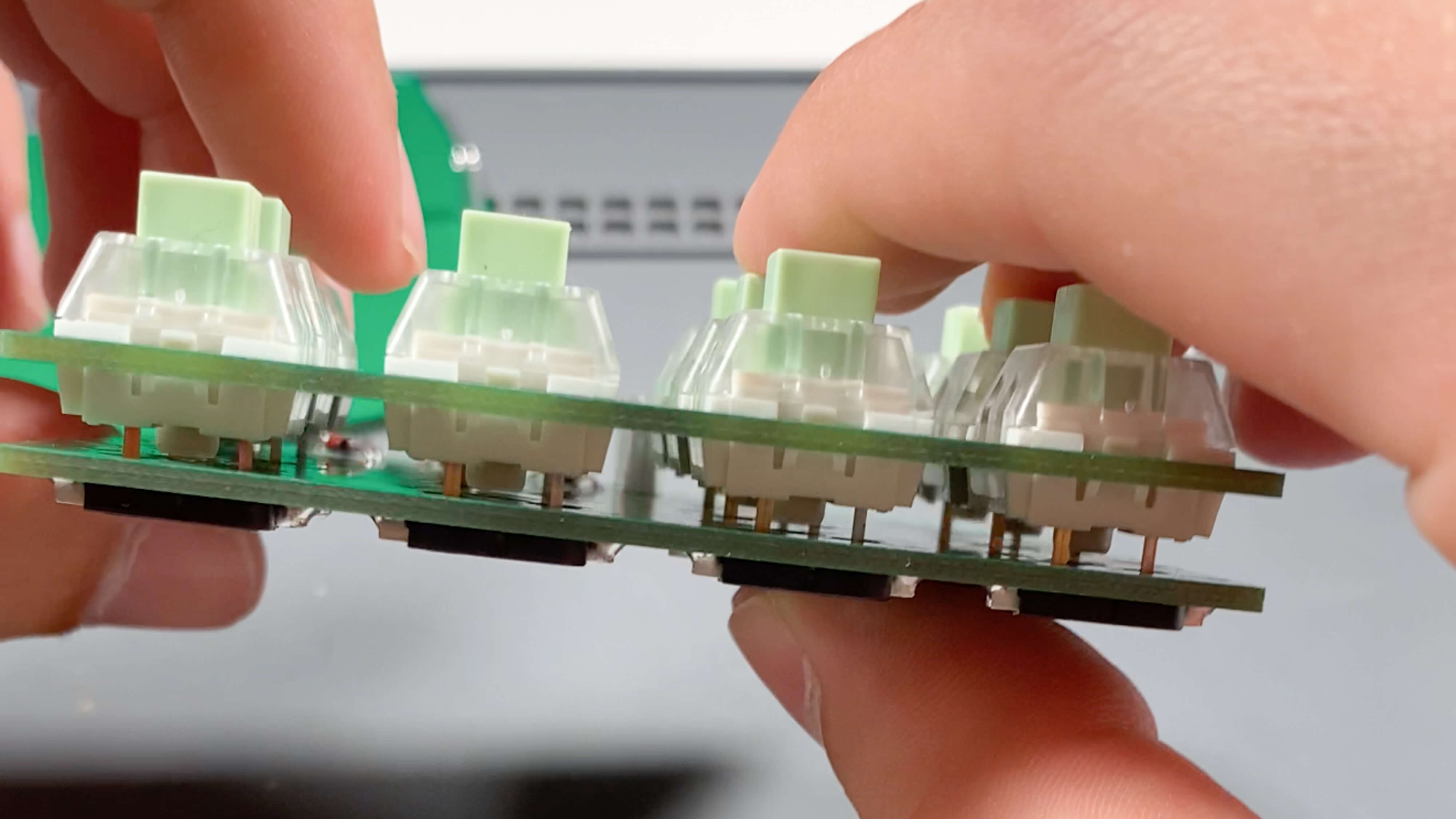
In order for final assembly to take place, we must marry the switches, switch plate, and PCB together. The 3x4 Macro Pad utilizes a floating PCB design so it is technically suspended, and the plate is what holds the PCB in place.
Bring the pieces together and line up the switch legs with the holes on the hotswap sockets. Firmly but carefully apply pressure as evenly as possible to press the switch legs into he hotswap sockets. Do small sections at a time and do not press down the entire way, keep doing this around the board until all areas are pressed down entirely.
It is possible to accidentally bend a switch leg, and that is okay, usually you can just remove the plate from the PCB and un-bend the switch leg and then try again. It happens to everyone.
Secure the Plate and PCB to the Backplate
Now we can make use of those 4 threaded standoffs we installed on the backplate. Place the plate_PCB assembly into place lining up the holes, and secure the plate_PCB assembly to the backplate’s threaded standoffs using 4 M2 screws through the plate. Do not over tighten.
Attach the Acrylic Cover
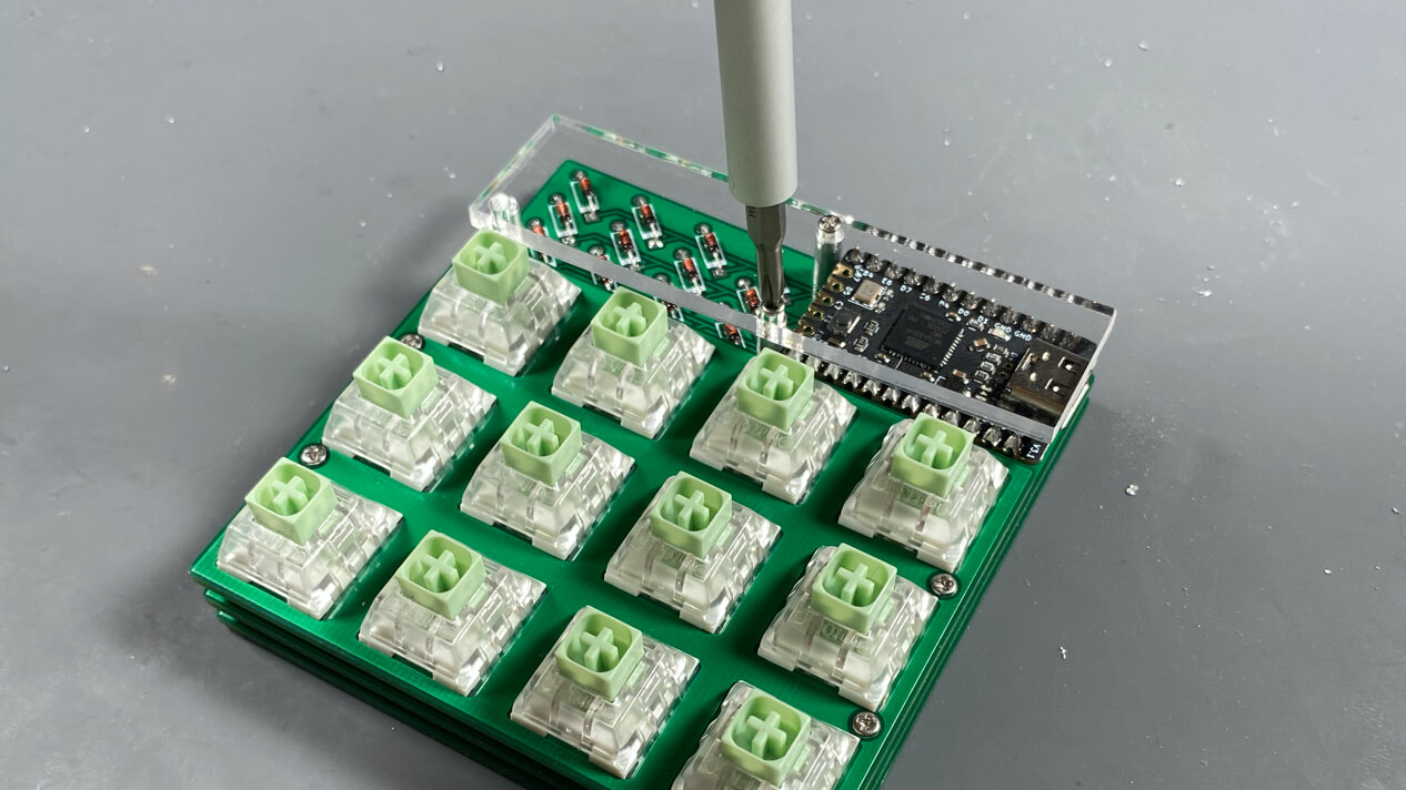
Finally, we can install the acrylic cover. The cover attaches to the three threaded standoffs protruding from the top of the PCB. Line up the holes with the standoffs, and loosely secure one at a time. Make sure to leave them slightly loose while you’re lining up the acrylic, then gently tighten each when the acrylic is completely in place. Be sure not to over tighten.
Install Keycaps
Install any MX Compatible keycap of your choosing onto the switches.
All Done!
If you’ve run into issues, come get some help in the Help channel in our Discord, or Submit A Ticket in the My Account section of Boardsource.