KLOTZ BUILDGUIDE
PART LIST
REQUIRED PARTS
| Part name | Count | Remarks |
|---|---|---|
| KLOTZ PCB | 02 | You can find the files for it here |
| KLOTZ switchplate | 02 | Which you can find here |
| nice!nano | 02 | Alternatively, you can use another controller with similar pinout and bluetooth capabilities like the Puchi-BLE |
| Choc key switch | 34 | Kailh Choc low profile keyswitches |
| diodes 1N4148W | 34 | These are surface mount diodes in SOD123 package |
| 1u Choc keycaps | 34 | You can use the black or white keycaps from Kailh, but I recommend MBK keycaps |
| reset button | 02 | Through-hole, 2 pin tactile buttons |
| power switch | 02 | MSK12C02 |
| EC12 encoder | 02 | Technically you could also use EC11 encoder, but flat EC12 like the EC12E2440301 will work best |
| encoder knob | 02 | Nearly every encoder knob, which works with the EC12 should work. But if you have acces to a printer you can use this one |
| USB cable | 01 | For connecting the keyboard with your PC |
| Lipo battery | 02 | You can use a variety of Lipo batteries, but the cutout in the switchplate is meant to be used with a battery which name ends with 2030, like the 902030. |
OPTIONAL PARTS
| Part name | Count | Remarks |
|---|---|---|
| MCU sockets | 04 | For socketing your MCU. Highly recommended |
| MCU pins | 48 | In combinatin with the MCU sockets |
| JST Jack | 02 | JST PH |
| switch socket | 34 | Switch sockets for Kailh choc switches |
| LEDs | 06 | 3mm through hole LEDs |
| resistors | 06 | R1206 220ohm SMD resistors for the LEDs |
| screws | 10 | 6mm M2 screws |
| bolts | 10 | M2 bolts |
| o-rings | 10 | as optional standoffs. OD4*1.5-150NB |
INTRODUCTION
Here is an overview of where and on which side each component needs to be soldered (click on the image to see a larger version).
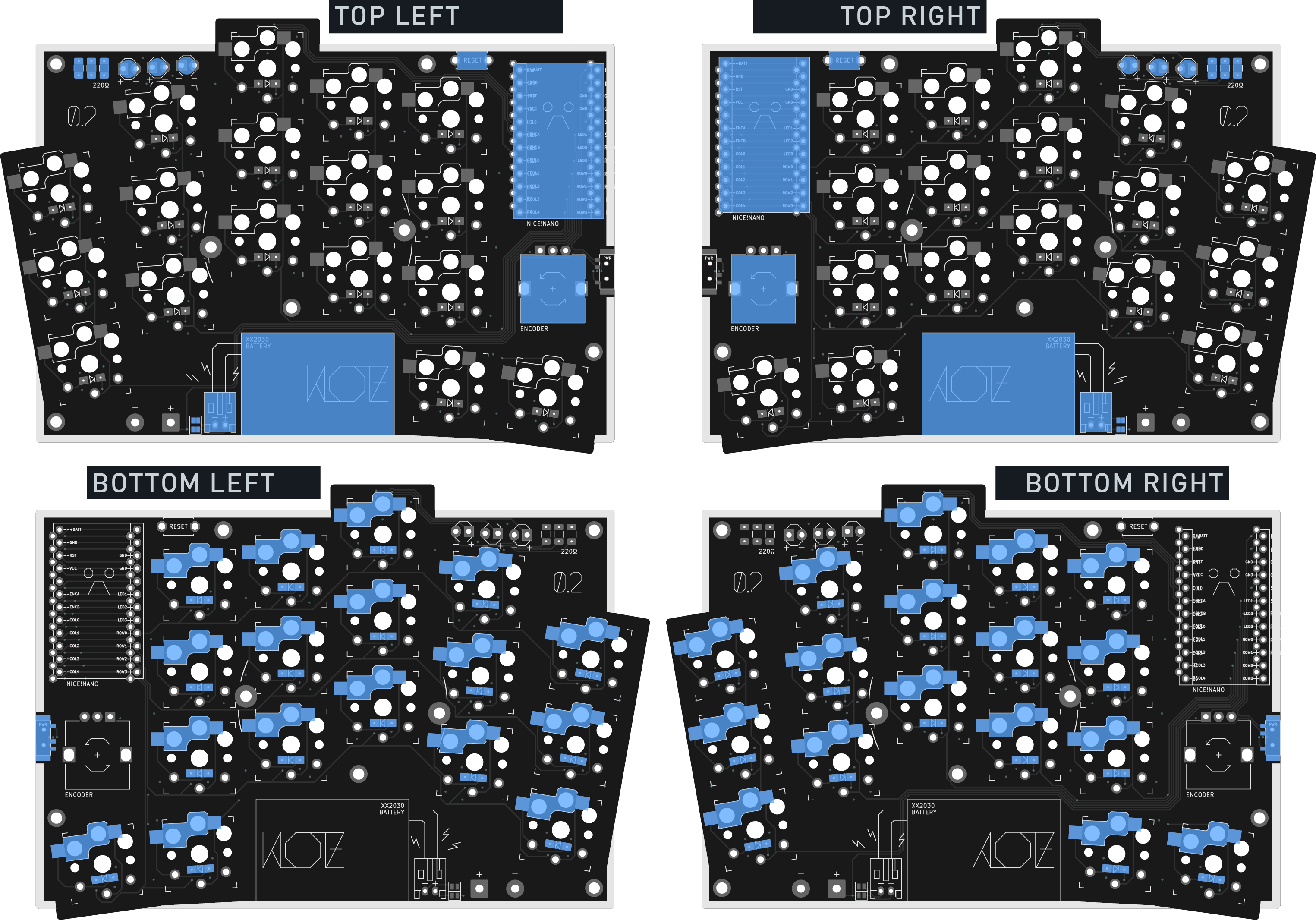
To see what component needs to sit where you can take a look at the interactive HTML BOM.
Warning This interactive HTML BOM does show where each component is located, but please still refer to the solder guide above to see if a component needs to go on the top or bottom of the PCB.
DIODES
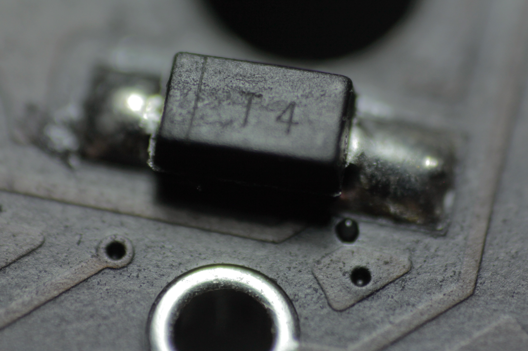
The diodes needs to be soldered on the bottomm of the PCB. Pay attention to their orientation: They have a small line on one side, which should be on the side the arrow on the PCB is facing to.

Apply a small amount of solder on one pad.\ Then use tweezers to place the diode on the pads and reheat the solder to secure the diode. Now you can solder the second pad.
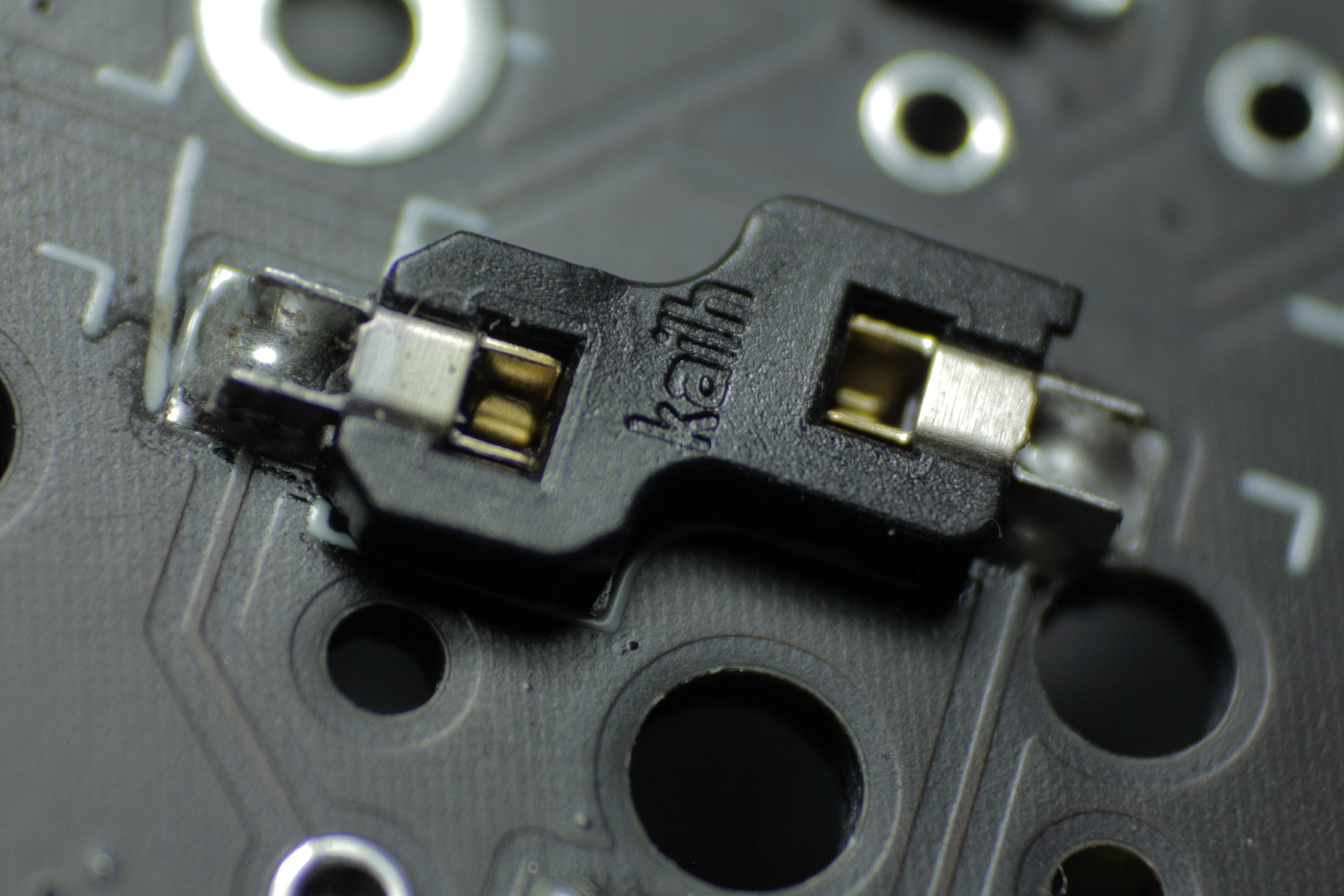
SWITCH SOCKETS
Here you can apply the same technique as used for the diodes: Apply some solder on one of the pads first.\ Then place the switch socket in the silk screen markings and reheat the solder. Apply some pressure with a pair of tweezers to make sure the socket is fully seated.\ Now solder the second pad.
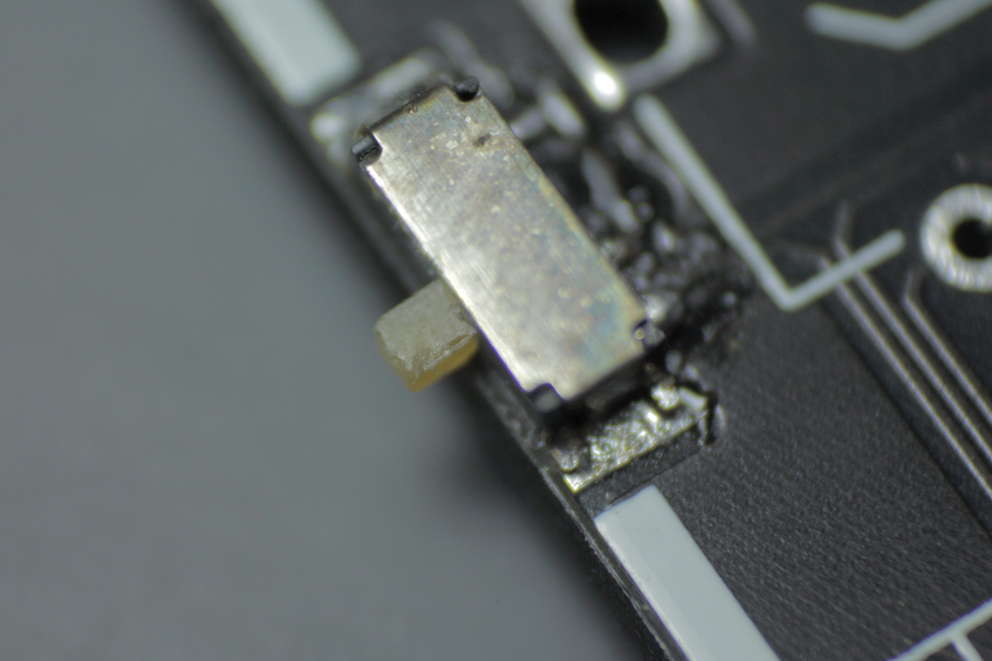
POWER SWITCHES
Apply a tiny bit of solder on one of the bigger, outer pads on the bottom of the PCB. The power switch has some tiny knobs on its bottom, which fits into the PCB holes. Hold it in place with tweezers and than reheat the solder on the pad. After this you can solder the other pad and the three pins.
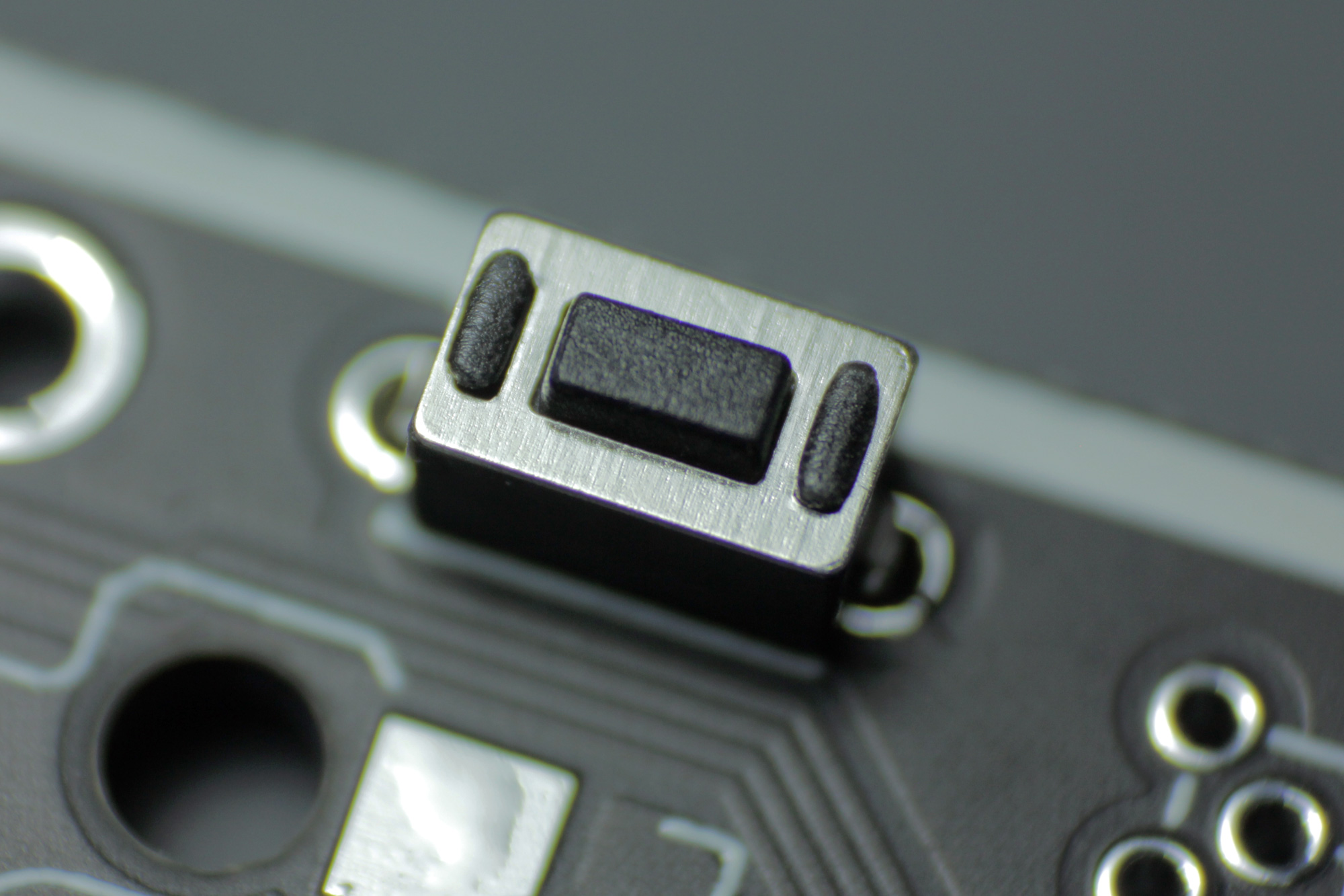
RESET SWITCHES
Put the legs of the reset switch through the holen on the top of the PCB. You can secure it with some tape, since you need to solder it from below.
MICROCONTROLLER
Warning First flash the microcontroller to make sure it works, before soldering it in.
The microcontroller needs to be mounted on the top, with the components facing downwards (to the PCB).\ Feel free to use the included header pins, but it's highly recommended to use MillMax low profile sockets.\ Place the sockets in the marked spots on the bottom side of the PCB. You can keep them in place by using masking tape.\ Then you can flip the board to solder in the sockets from the bottom.
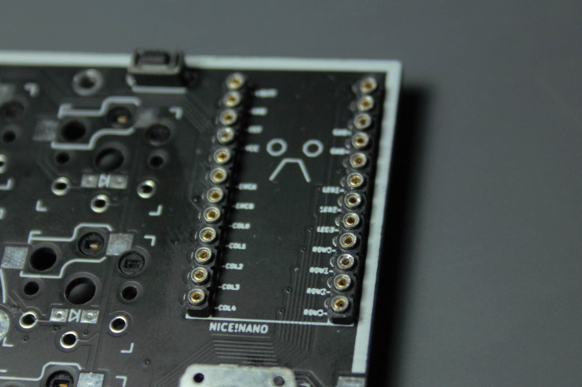
Insert the pins into the sockets.
Note Use tweezers to insert them. Don't apply too much force, you will feel them snap in. After that, you can carefully apply some pressure, using a flat object to make sure they're fully seated.
Now place your microcontroller on the pins (components facing the PCB) and solder it to them.\ You can use flush cutters to trim the header pins.
Warning When trimming with flush cutters wear eye protection or hold your hand close above the pins. Otherwise sharp metal pins flying around might hurt you.
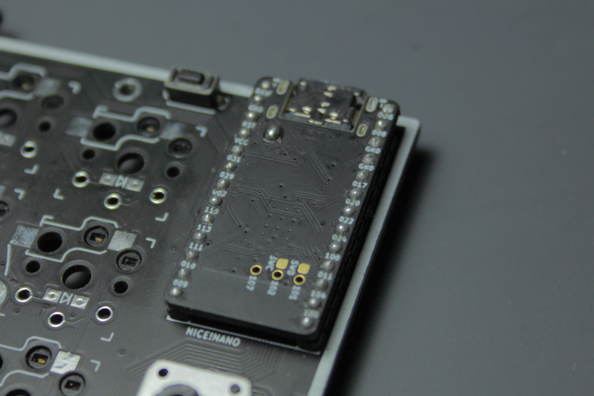
Warning On this image you can see the charge boost jumper of the nice!nano bridged. This increasesd the max charge rate from 100mA to 500mA. Only do this if your battery is at least 500mAh, to avoid explosions.
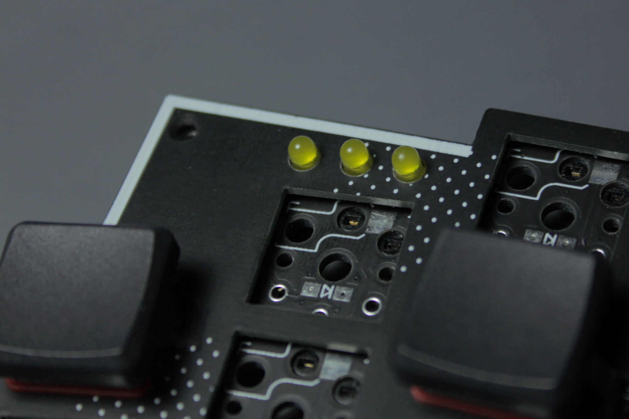
LEDS (optional)
Insert the LEDs from above. It helps to use the switchplate to align them, but you need at least two switches to fixate it. This way you can make sure they won't get in the way later.
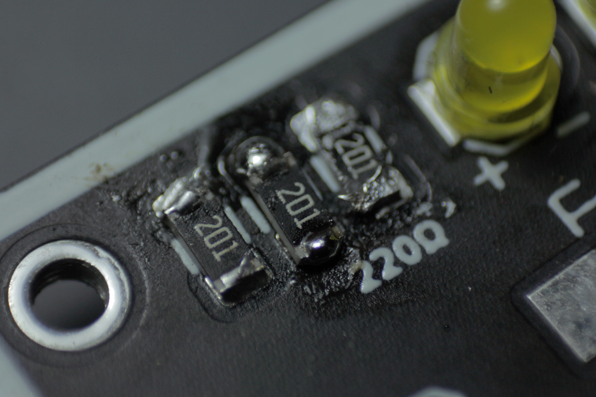
RESITORS (optional)
Than you should remove the plate and solder the tiny resistors next to the LEDs. As you can see here I still haven't a good technique at hand for doing this.
ENCODERS
Note Currently ZMK only supports encoders on the primary side of split keyboards.
Mount the rotary encoder on the top side of the PCB. It should click into place maybe requiring a firm press. If it's seated correctly solder the pins on the bottom.

JST (optional)
You don't need to solder a JST jack, but it makes it easier to connect and deconnect your batteries, if they already got a JST plug.
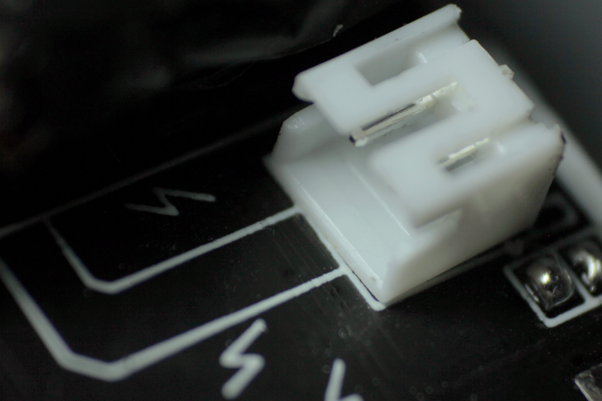
If you plan to use a JST jack you also need to bridge the jumpers on the top, next to the JST jack.
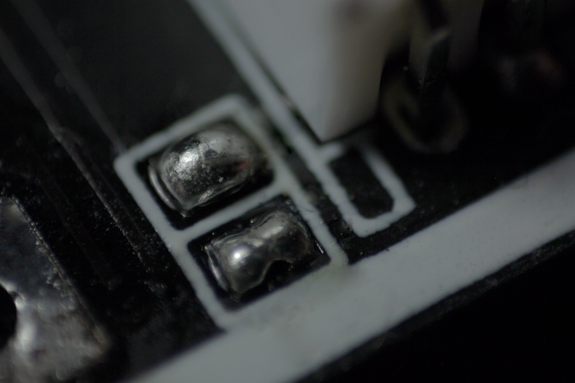
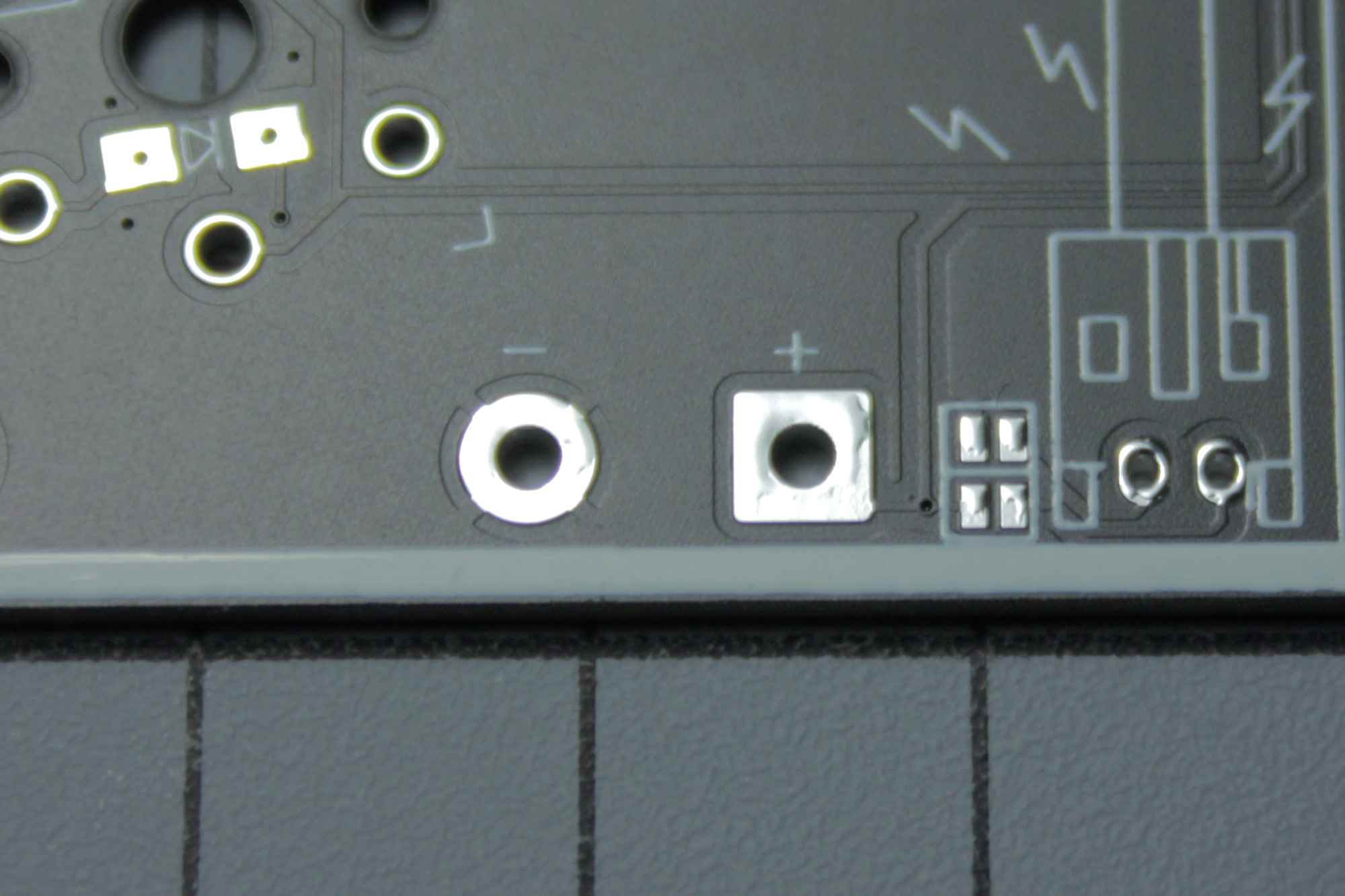
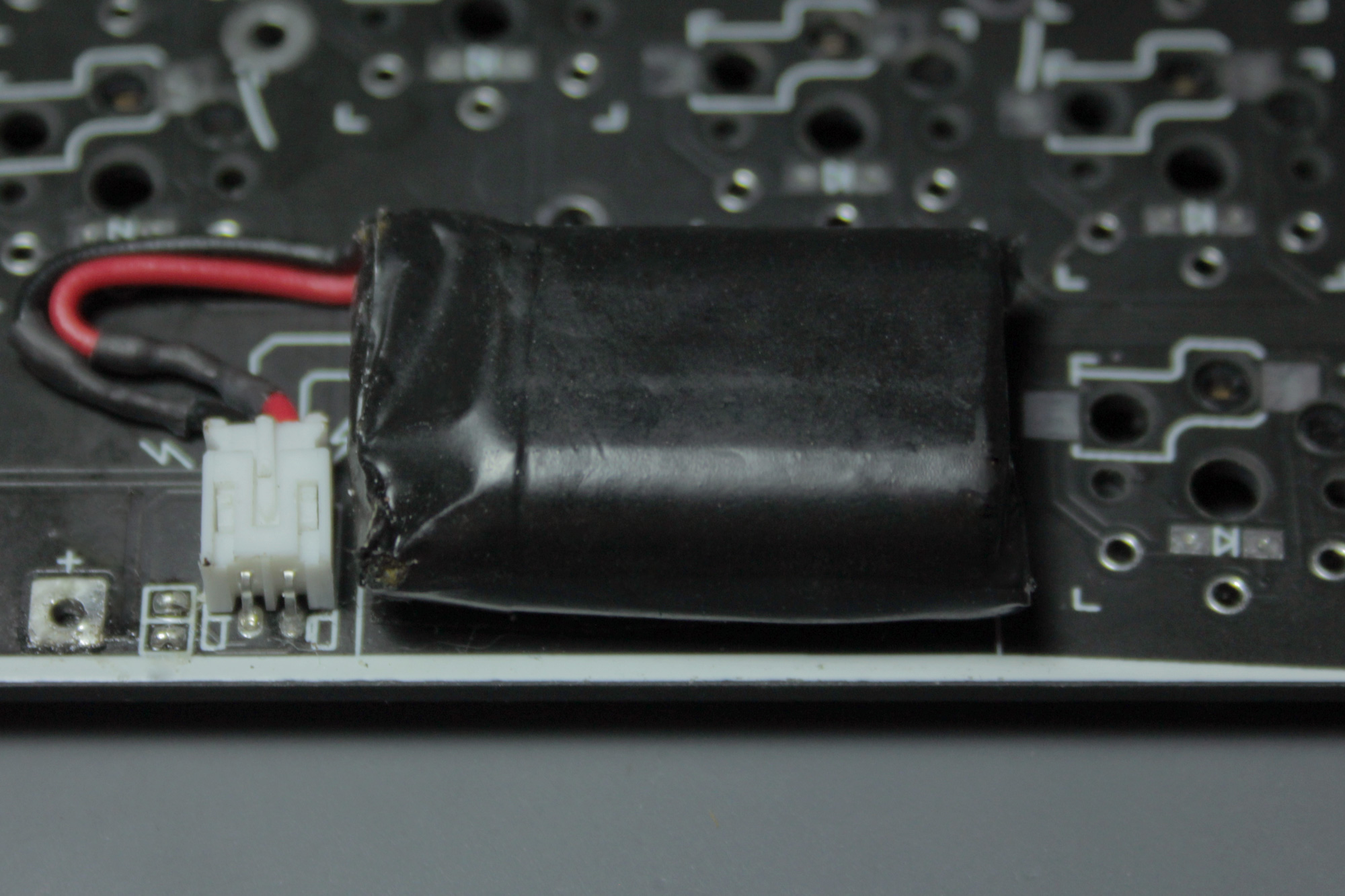
BATTERY
If you don't use a JST jack you can solder the wires of your battery to these pads. Red to Plus and Black to Minus.\ In this case you don't need to bridge the jumpers.
You should use double-sided tape (or even double sided foam tape) to attach the battery to the PCB. You can use the switchplae to align it.
(by the way I plasti-dipped mine, since I dislike the default silver color)
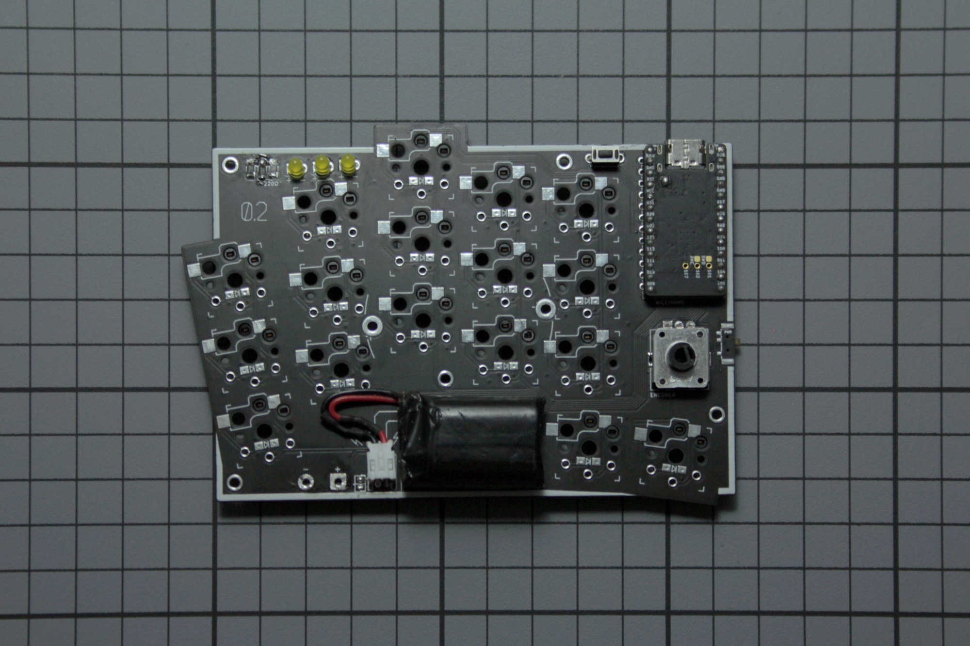
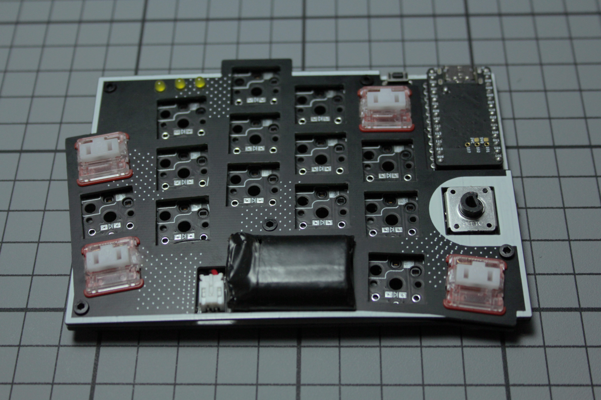
CLEANING
This is how your finished PCB probably will look like. You can use an old toothbrush and some isopropanol to clean it from residues.
FIRMWARE
If you have not already flashed the firmware to the microcontroller you should do it now, to make sure everything works, before inserting everyting into the case.\ Here you can find the ZMK firmware for the KLOTZ.\ You need to create an own fork of it. In this fork you can edit the keymap to trigger an Github action, which will create your firmware.
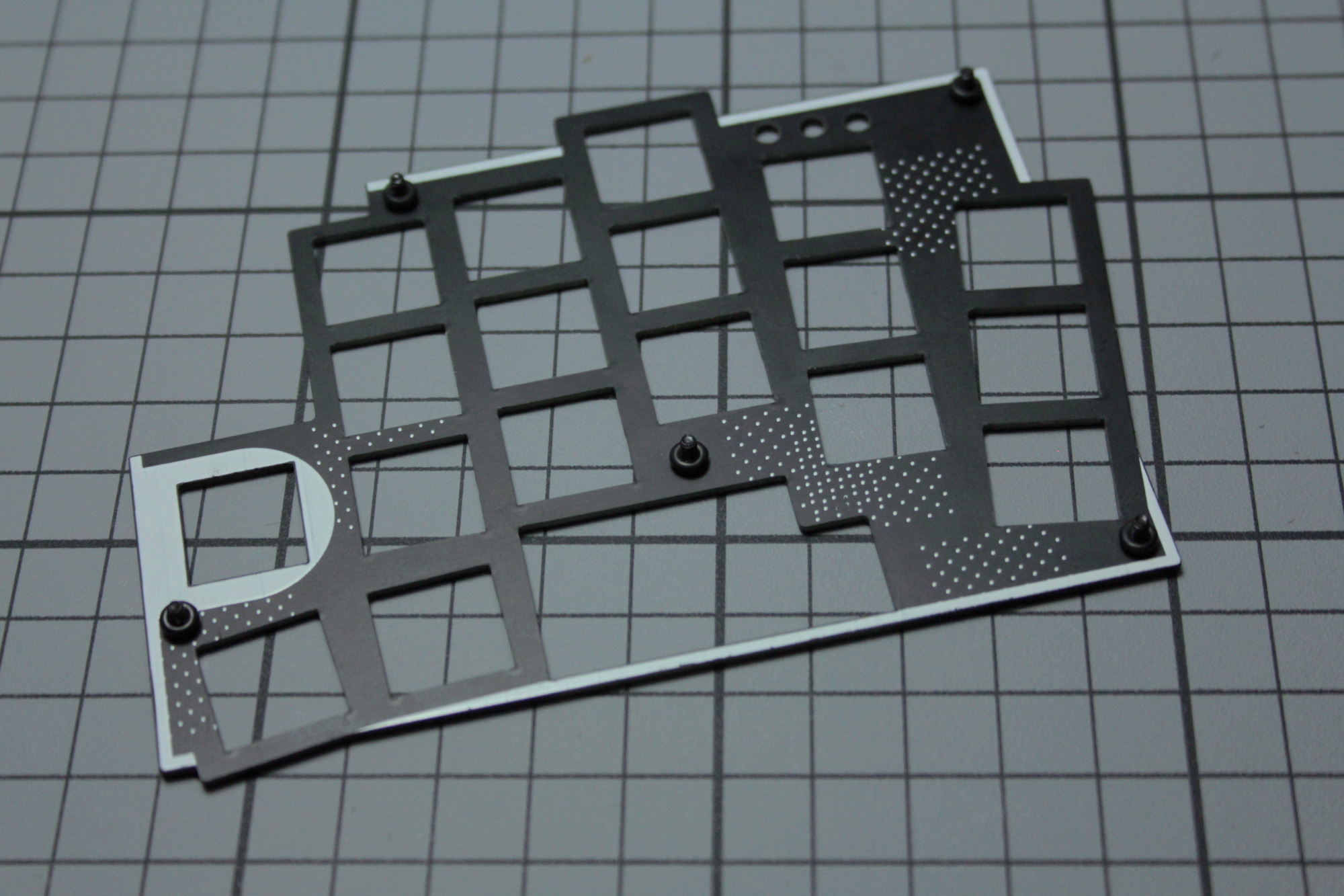
SWITCHPLATE
Since there isn't much space beween switchplate and PCB on choc builds you don't really need screws, but if you use them I recommend O-rings, which are meant to act as spacer between PCB and switchplate. Thick and small ones seem to work best in this case.
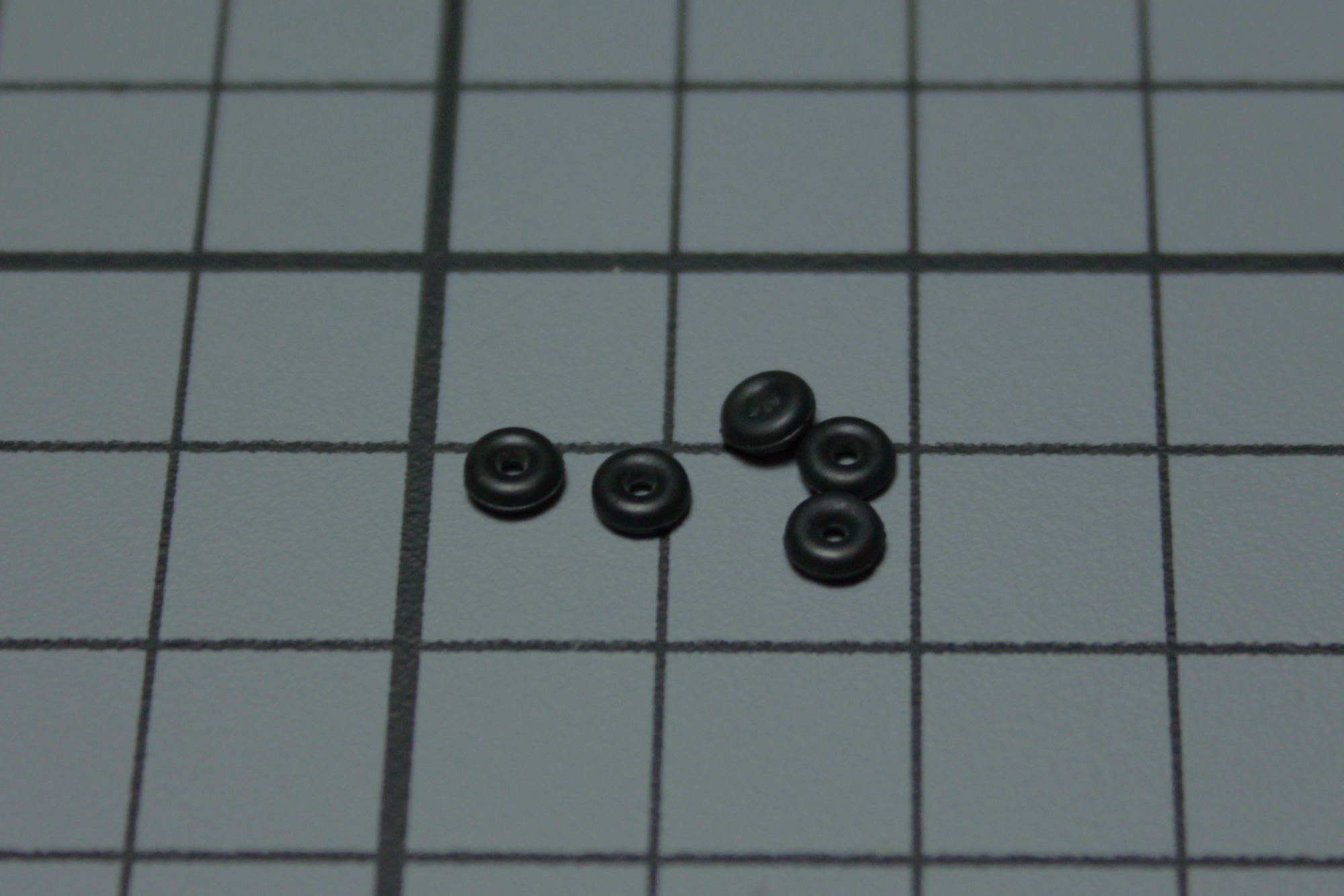
Insert the screws into the holes of the switchplate and use tweezers to secures them with the O-rings.
Attach the plate to the PCB and use some switches to keep it in place, so you can secure it from the bottom with bolts.
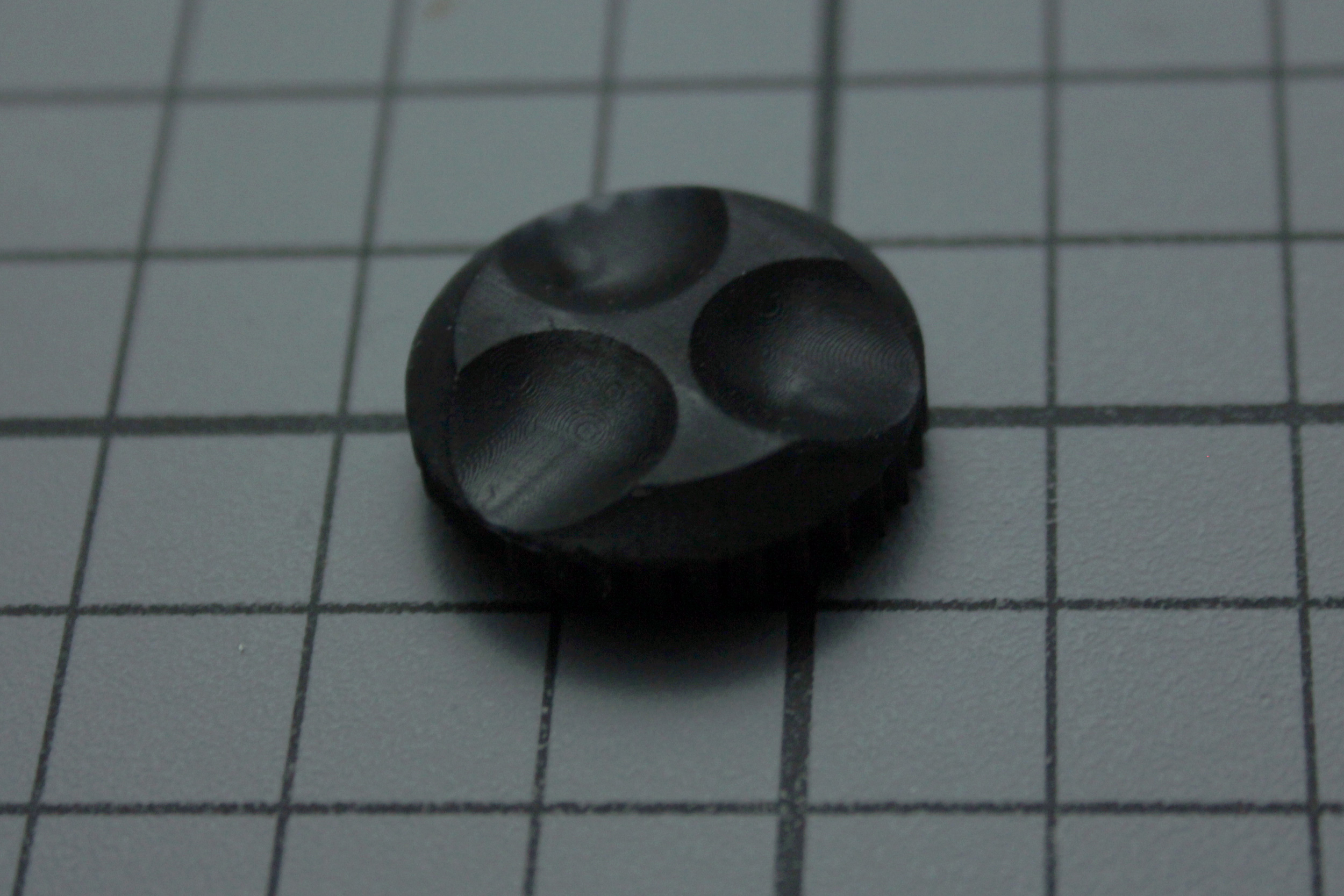
KNOB
This is the 3D printed knob you can find here.
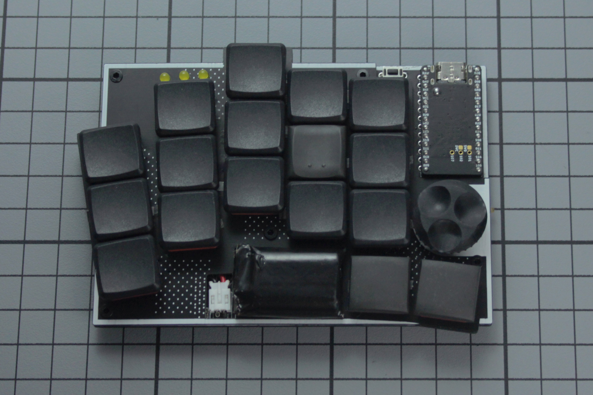
FINAL BUILD
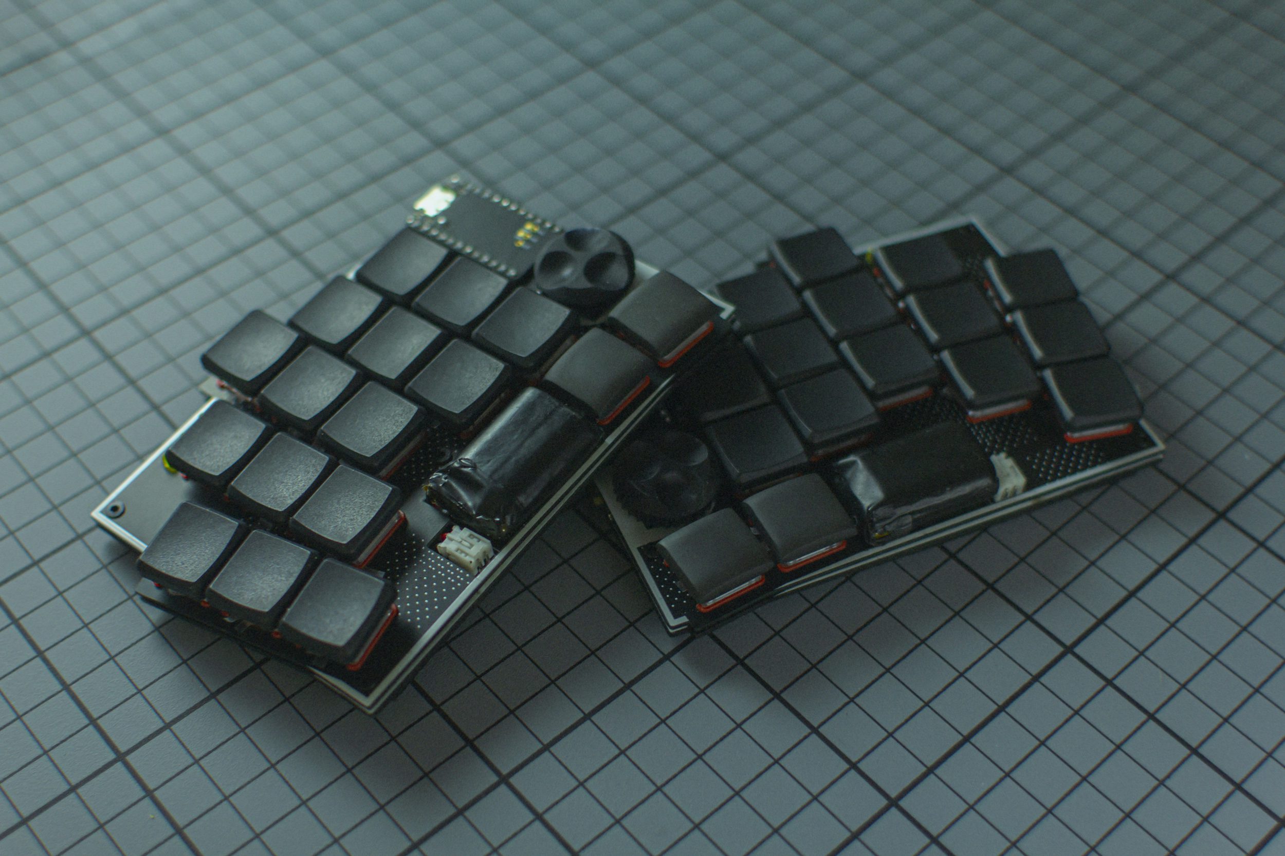
Insert the rest of the switches and put some keycaps on.\ In this picture you see it with Pseudoku CS keycaps on homing keys and thumbs, the other keycaps are MBK blanks.
Here are some links to other articles that may help you get the most out of your new keyboard:
- Get the most out of your PCB Unleashing the High-Tech Power of Custom Keyboards
- Keyboard Programing
Extra
For questions, ask in Boardsource Discord server