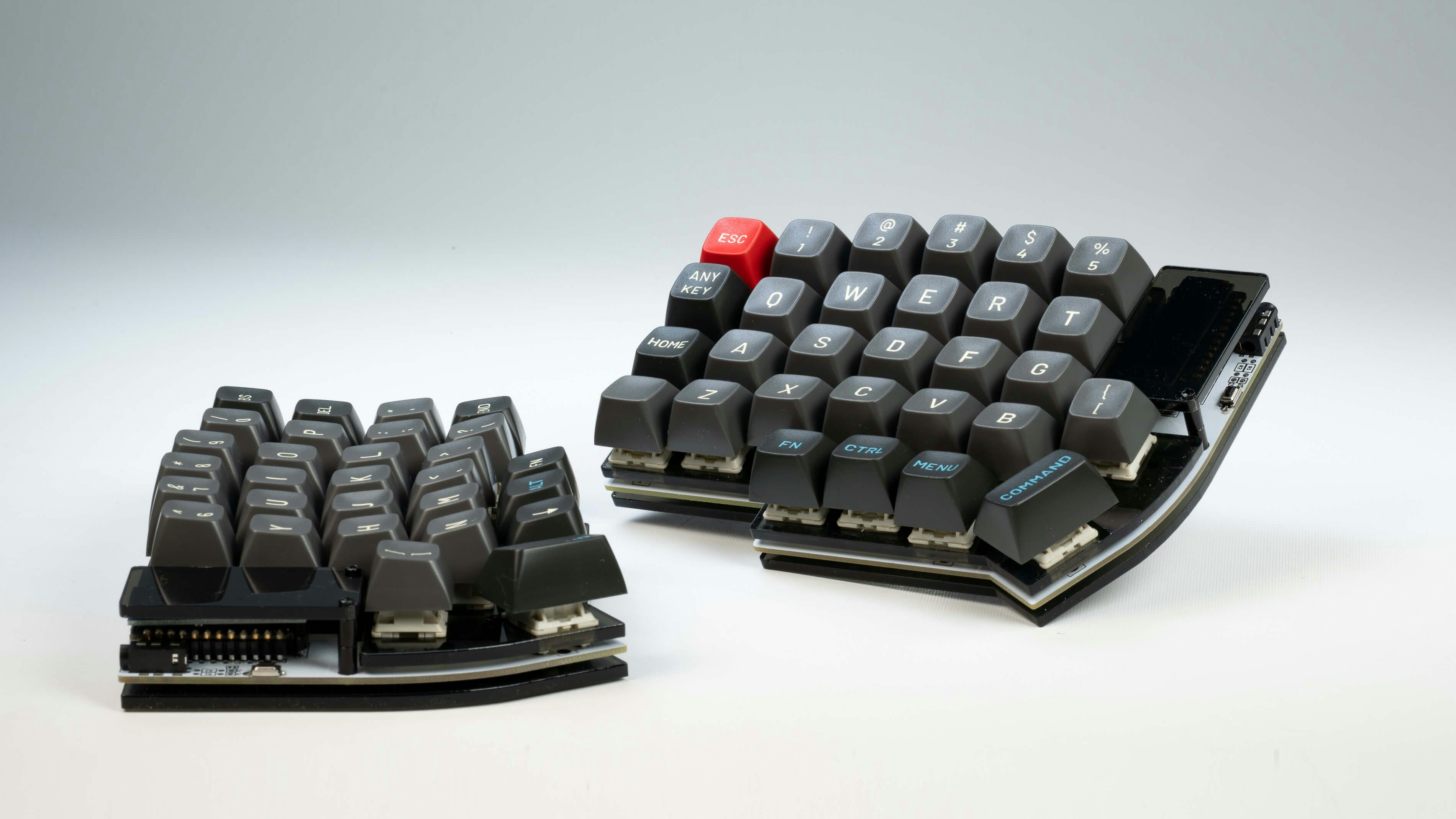
DracuLad Build guide
What you need
- 2x pcbs
- 2x bottom plate, 2x top plate
- 34-36 switches, either choc low profile v1 or mx compatible ones
- 2 rotary encoders
- 2x pro micro compatible controllers
- 38x sod123 SMD diodes
- 2x reset switches
- 2x TRRS jacks
- 8x 0.7cm standoffs, 16 m2 screws to mount the case
- usb cable, trrs cable, rotary encoder knobs, keycaps
What you optionally need
- 2x extra rotary encoders (for the thumb cluster, each additional rotary encoder decreases the needed switchcount by one)
- 20x ws2812b LEDs (if you want underglow)
- 2x SSD1306 OLEDs (128x64)
- 2x OLED cover
- 6x standoffs with m2 screws for the OLED cover (standoff size depends on whether you use the OLEDs or not and probably also how low profile your pro micro is mounted (bit-c for example is a bit higher profile), with OLEDs 1cm is ok)
- 1x pimoroni trackball (this will only fit for the plateless build or the one with the FR4 plate)
First step: solder the Diodes
- the diode mark should be aligned with the mark on the PCB
- solder the diodes on the bottom of the PCB, the PCBs are reversible, therefore you need to decide for one side in the beginning
- put solder on one of the pads, reflow the solder while sliding the diode into place, solder the second side of the diode
Second step: solder the LEDs
- the little triangle on the LED should allign with the triangle on the PCB
- do it similar to the diode, first solder one pad, slide in the LED, solder the other 3 joints
- be careful, those things are really heat sensitive, only ever touch the metal part with the iron, never the plastic - if possible, don't touch the LED with the iron but let the solder flow onto the joints
Third step: install the pro micros
- before installing the pro micro, flash it with the right firmware which can be found on the qmk master or, if you're using a bluetooth controller like the Nice!Nano or the nRFMicro, refer to my fork of the zmk firmware which should implement some basic features on the "draculad"-branch.
- the pro micro headers/sockets should be in the outlines marked on the PCB
- now is the right time to plug in your keyboard and check whether everything works - if you did everything right, every switch - besides the ones that switch layers (refer to the layout in the firmware) - should give you a feedback and all the LEDs should light up red. The LEDs are daisy chained, so check them by correcting them one by one in the chain that starts at the bottom of the pro micro and follows all around on the edge of the PCB
Fourth step: Install your Pimoroni, OLEDs, Encoders
-
for the OLEDs, jump the OLED jumpers on top of the PCB and solder in the OLEDs. Add some insulating tape on the bottom of the OLED to avoid shorts with the pro micro, after that just solder them in, there's not much you can do wrong here
-
test them by pluggin in, they should both come on
-
for the pimoronis you should not compile the default keymap but rather the "pimoroni" one
-
jump the pimoroni jumpers on top of the PCB
-
before soldering the pimoroni, make sure you insulate it with a bit of insulation tape
-
solder the pimoroni in if applicable
-
the pins should be as flush as possible with the top of the pimoroni pcb
-
the pimoroni pcb should be parallel to the draculad pcb
-
to optimize the profile, use diode pins to connect the pimoroni to the pcb
-
after plugging in, your trackball should light up red and work now
-
clip away the short, thick legs of the encoder (!NOT THE PINS!) and solder them into the spots you want them
-
remember, all 4 encoder spots are supported at once
Fifth step: Take a break
At this point you should have a fully working keyboard barebone. Test the
encoders and whether there are any errors plugging in the keyboard. Both OLEDs
should work, as well as the LEDs and the Pimoroni. If not, try to correct your
mistakes, don't lose your temper, most of the things can be corrected very
easily. If you're debugging your keyboard under Linux, you can test the keys and
the encoders by using xev -event keyboard and whether the keyboard is
correctly recognized with dmesg --follow -H. (Mind that you need proper
rights to run this command.)
In the improbable case you're using nix, you can get the keyboard tester with
nix-shell -p "xorg.xev" --run "xev -event keyboard"
Sixth step, solder in the switches
- depending on whether you build it with or without plate, stick the switches through the plate and then through the pin holes. Solder the pins.
- mount the OLED cover, use the longer standoffs for that
- screw the shorter standoffs to the switch plate and then to the bottom plate
- mount keycaps
Firmware
QMK
In qmk this keyboard can be found under draculad To begin, follow the QMK setup guide. (if working from an existing installation, an update may be needed.) \ For flashing instructions, see doc or video
KMK / PEG
In Peg or KMK this keyboard can be found under draculad
Peg can be downloaded here, and the quick start can be seen here.
For Kmk can be downloaded here and the quick start can be seen here
Here are some links to other articles that may help you get the most out of your new keyboard:
- Get the most out of your PCB Unleashing the High-Tech Power of Custom Keyboards
- Keyboard Programing
Extra
For questions, ask in Boardsource Discord server