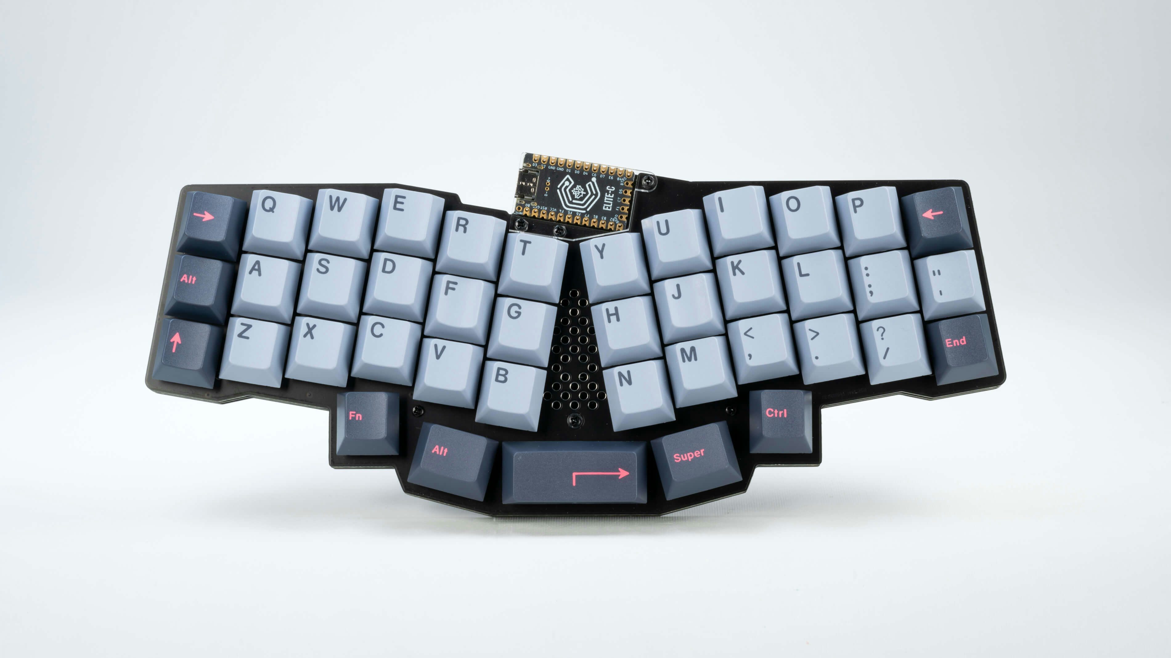
REVIUNG41 Build Guide
build guide
Parts included in the kit
| name | number | remarks |
|---|---|---|
| PCBs | 1 | Main PCB |
| Top plate (PCB) | 1 | PCB with switch mounting holes |
| bottom plate | 1 | FR4 |
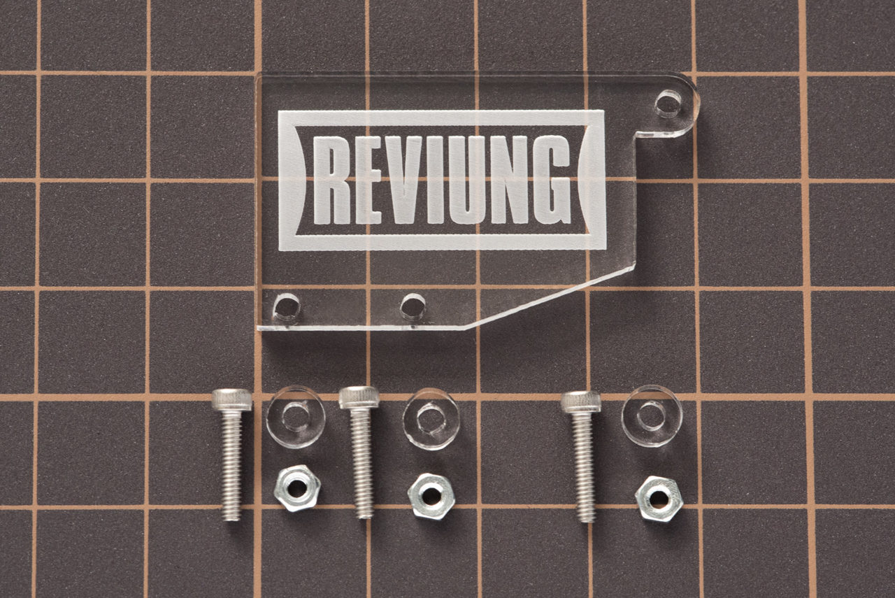
| ProMicro protection plate | 1 | acrylic |
| acrylic nuts and bolts | 3 | steel nuts and bolts |
| case stand offs 8mm | 11 | aluminum stand offs |
| M2 screw 4mm | 22 | For top/bottom plate connection |
| rubber foot | 6 | for bottom plate |
| Diode (1N4148 SMD) | 41 | |
| MX Hotswaps | 41 | |
| Tact switch | 1 | reset switch |
| Tact switch | 11 | |
| Durock 2U stabalizer kit | 1 | |
Required parts other than the kit
| Pro Micro compatible MCU | 1 |
| Switches | 41 |
| Keycap (1U) | 36 |
| Keycap (2.25U) | 1 |
| Keycap (1.25U) | 4 |
| USB-C cable | 1 |
assembly
The general flow is as follows.
-
First prepare the ProMicro and write the firmware. Flashing guide
-
Solder the reset switch.
-
Solder the LEDs one by one while checking the operation.
-
Solder the diode.
-
Solder the HotSwaps sockets for the switches.
-
Attach the stabilizer to the main PCB.
-
Attach the stabilizer to the main PCB.
-
Install the top plate, PCB and bottom plate.
-
Install the switches.
-
Attach the keycaps and you are done.
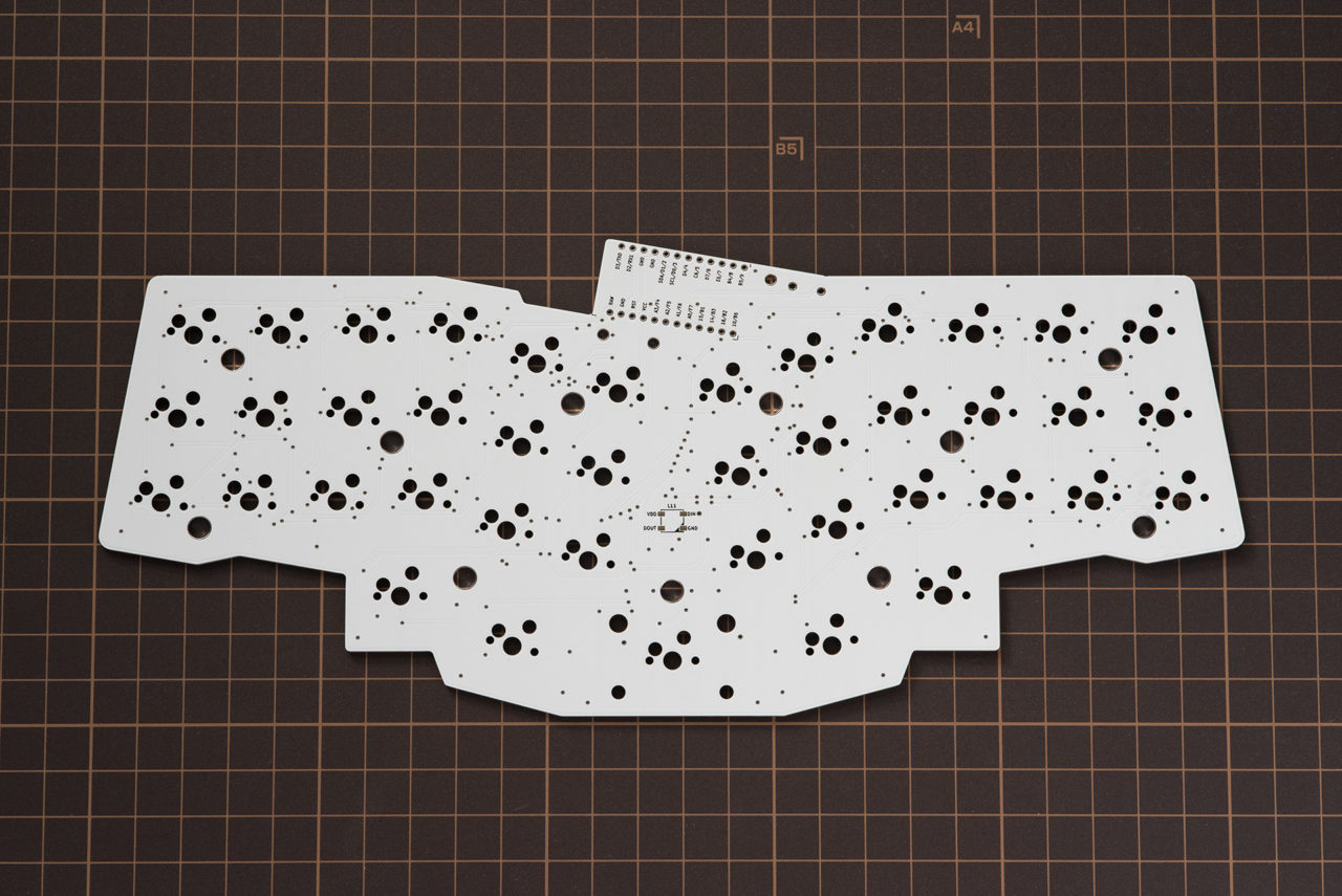
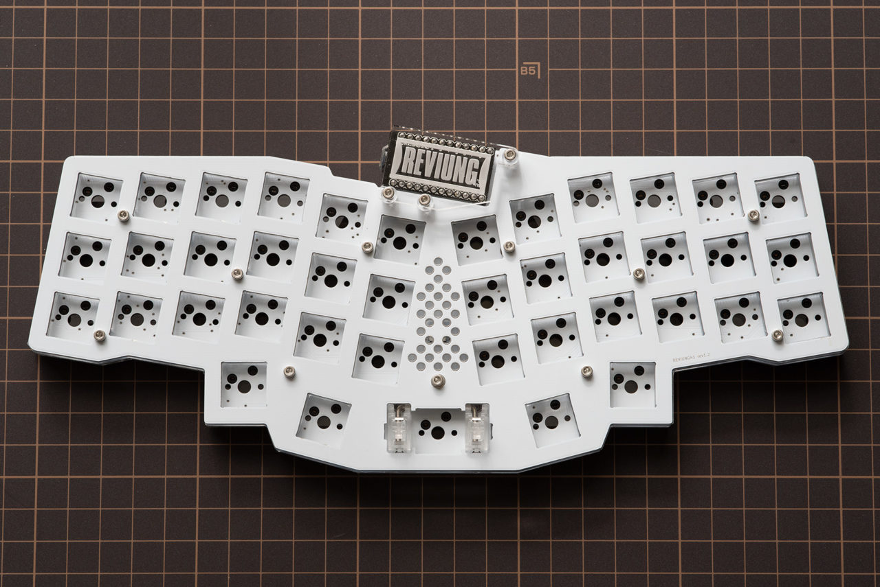
pcb front before soldering
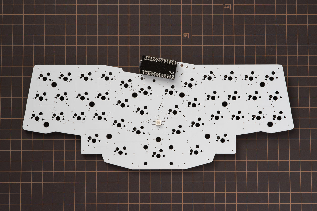
pcb front after soldering
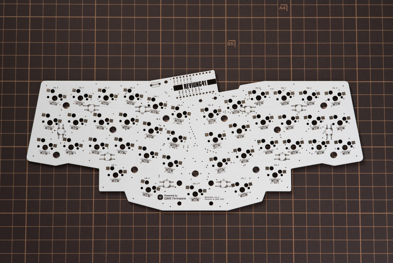
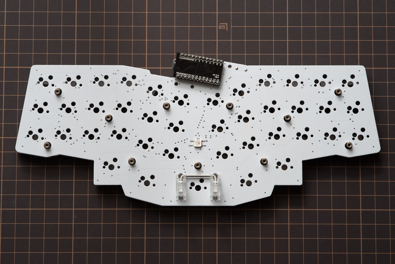
pcb back before soldering
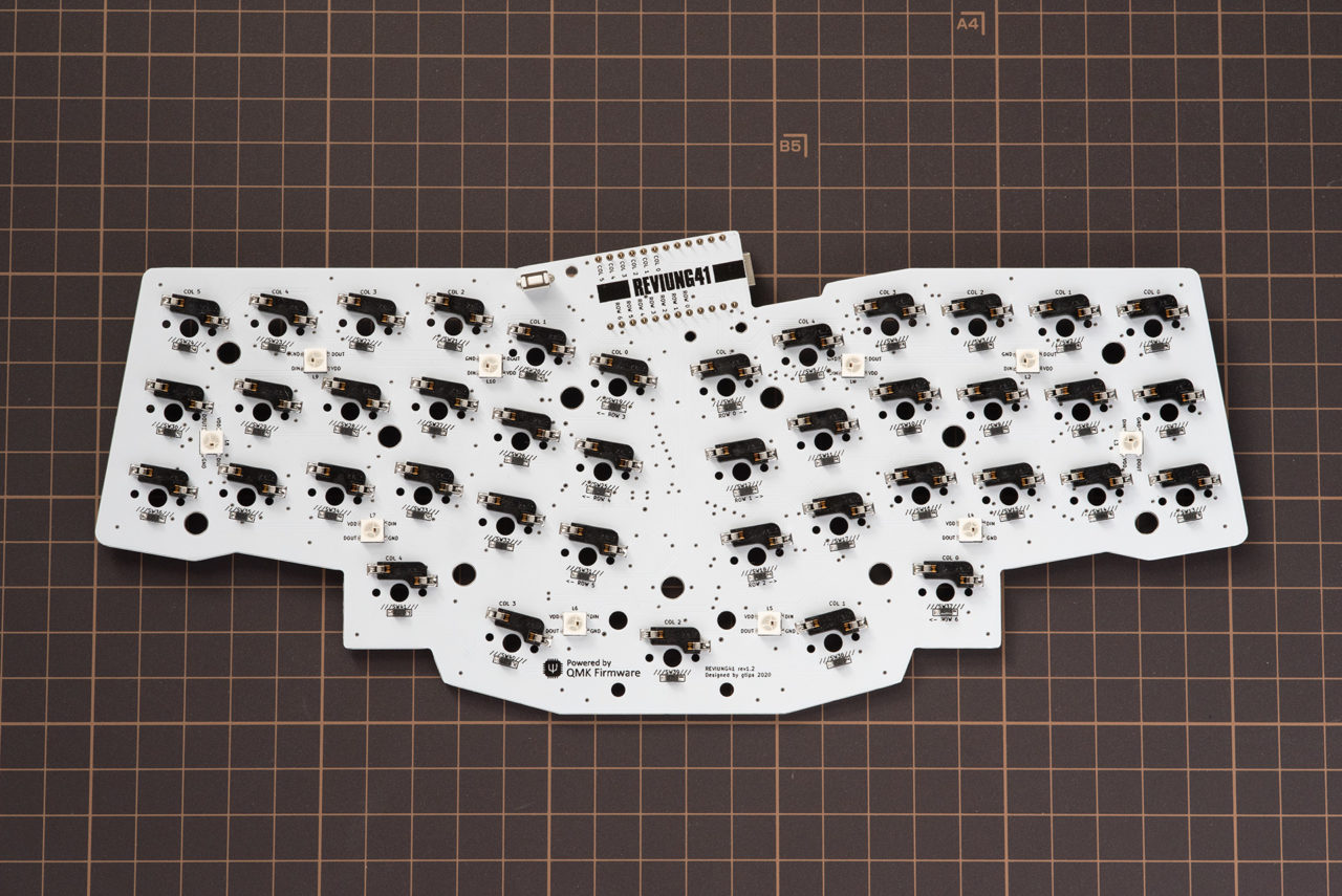
pcb back after soldering
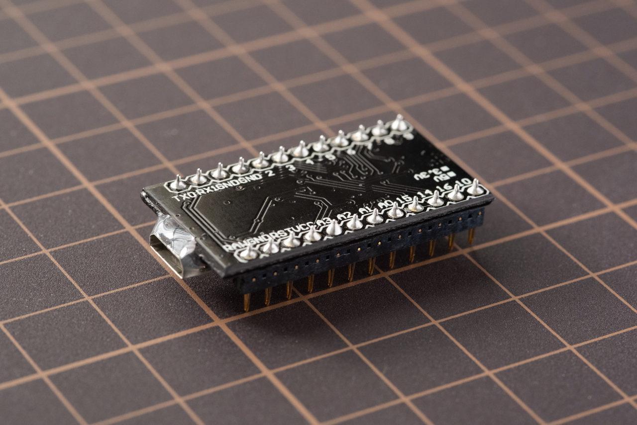
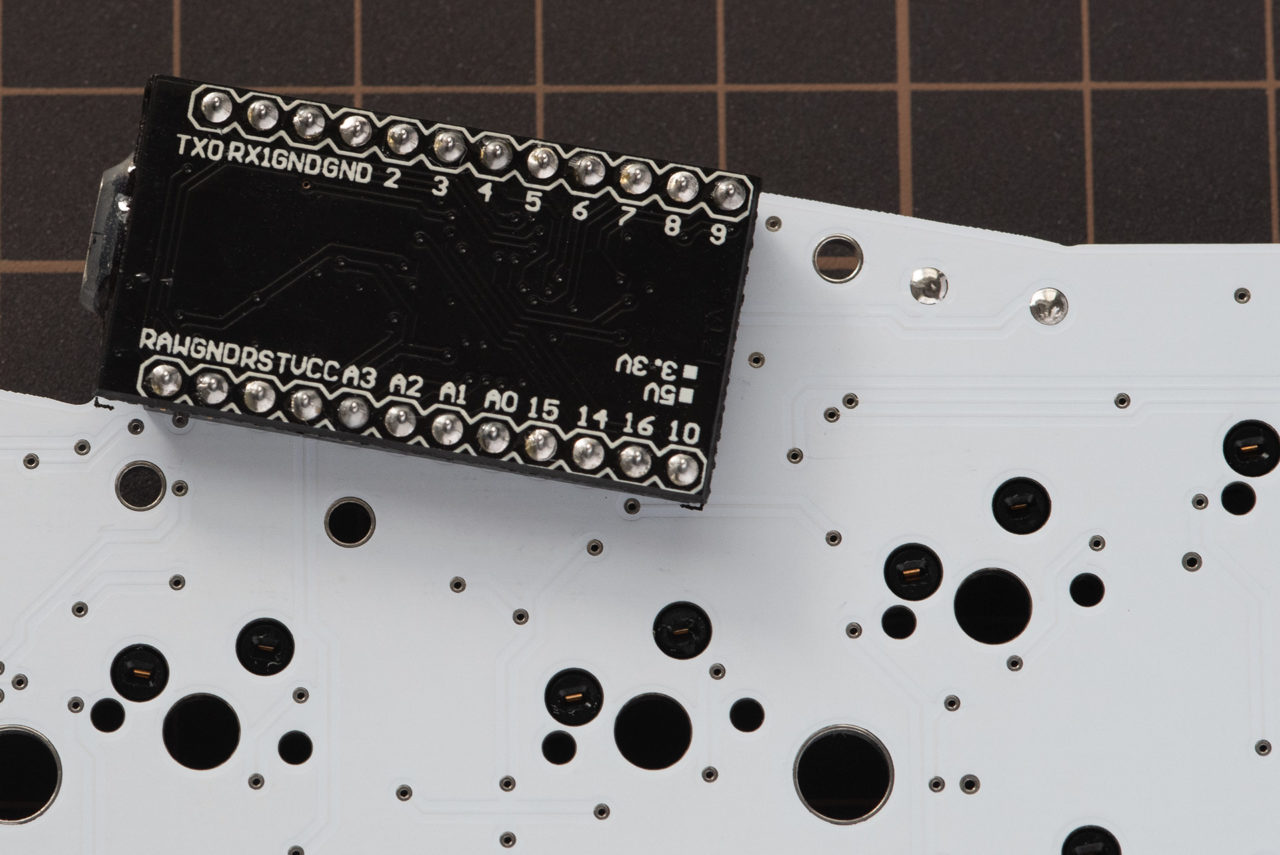
Solder the through (spring pin header) to the ProMicro. (Recommendation)
Alternatively, solder the pin headers to the ProMicro.
There is a recommended mounting direction for the con-through.
Conthrough has a side with a hole and a side without a hole , and there is a side with a hole closer to the pin and a side farther from the pin.a
When mounting, make sure that the two small windows face the same direction , and insert the hole closer to the pin into the ProMicro
Stick the through through the side of the ProMicro chip and solder it from the other side.
Soldering is only on the ProMicro and the through side. Do not solder the PCB
and the con-through. 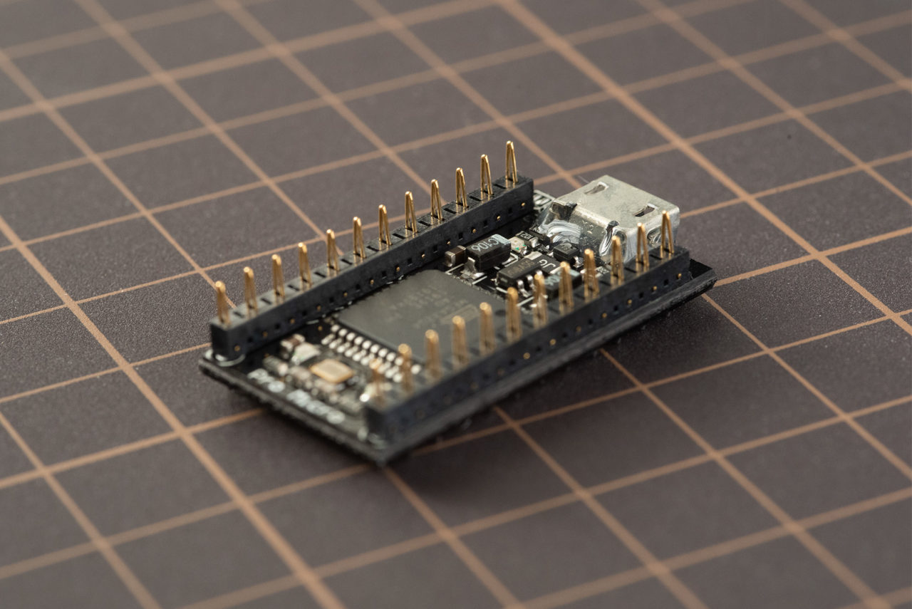
When using a pin header
Even if you use a normal pin header instead of a through hole, pierce the pin header on the surface where the ProMicro chip is mounted and solder it.
Also, if you use a pin header, solder the PCB side as well.
Soldering the reset switch
Then solder the reset switch to the PCB. Solder the tact switch to the part
marked "RESET" on the back of the PCB. *Refer to the photo of the soldering
completion image (back side of PCB) when soldering 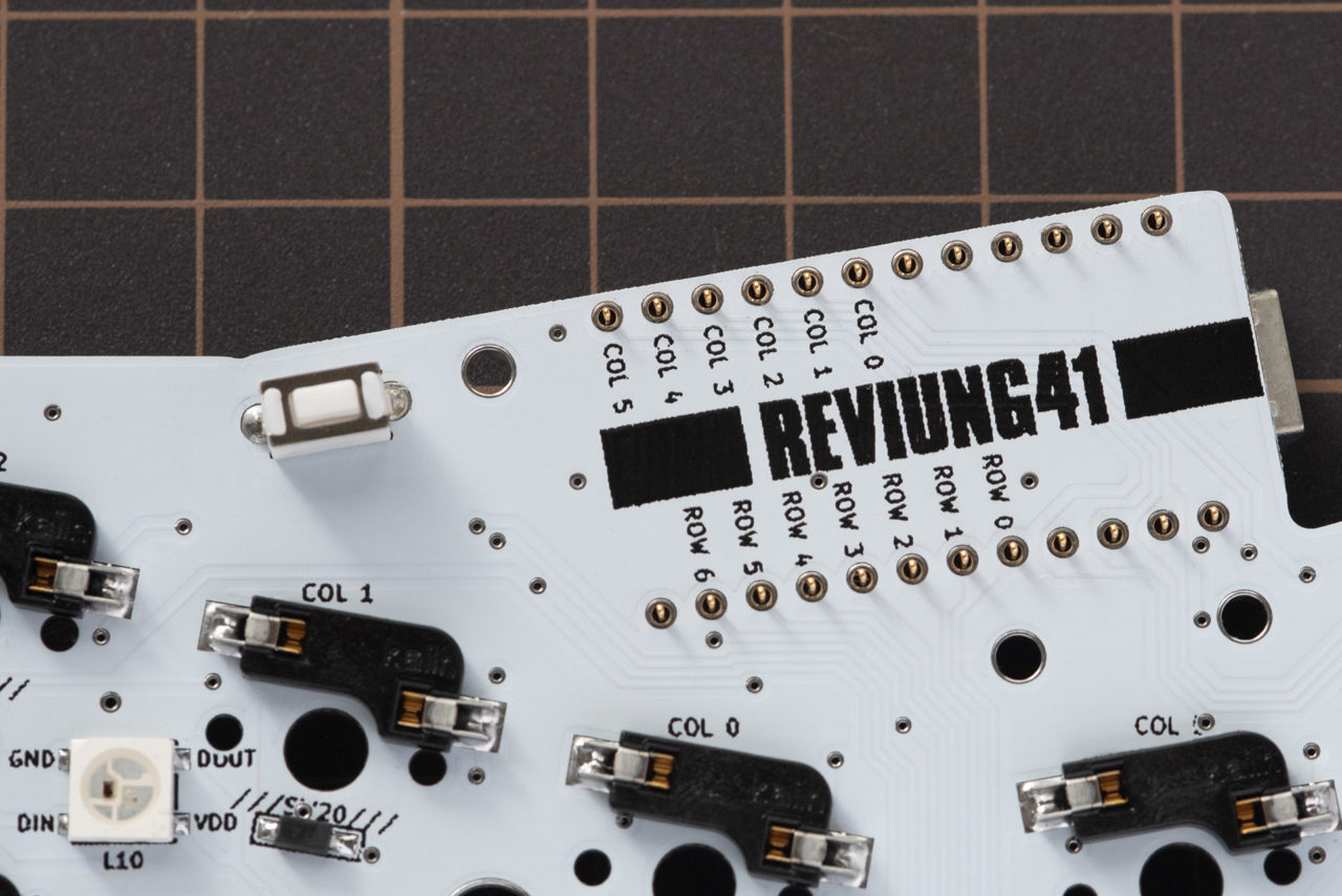
Attach the ProMicro to the PCB, connect it to your PC with a USB cable, and prepare to write the firmware.
Solder the LEDs while checking the operation one by one.
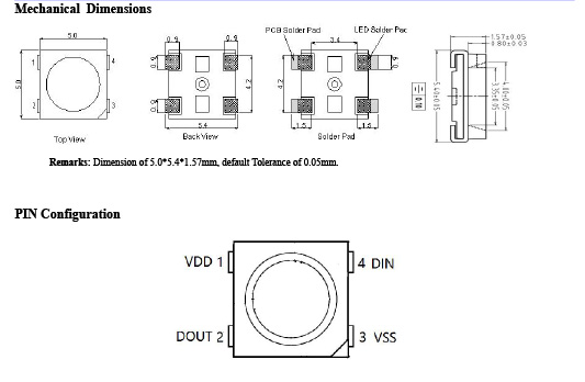
Solder the LED (WS2812B).
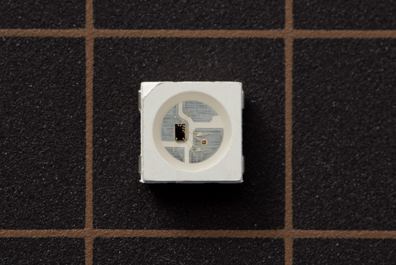 The REVIUN41 uses a 5050 size chip called [WS2812B].
Use a soldering iron with a temperature control function and work at a temperature of about 320°C. (If the temperature is too low, it will take time for the solder to melt, making the work difficult.)
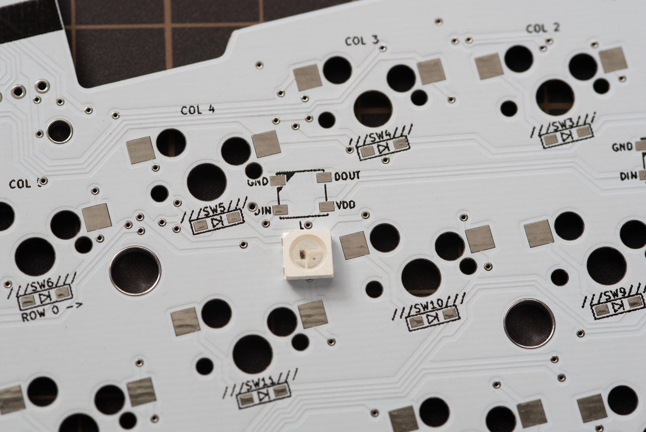
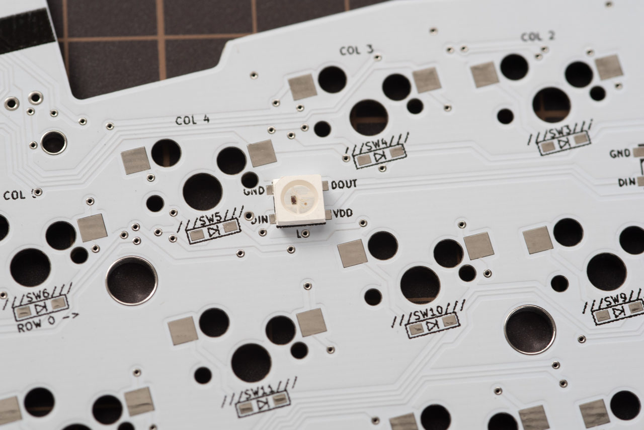
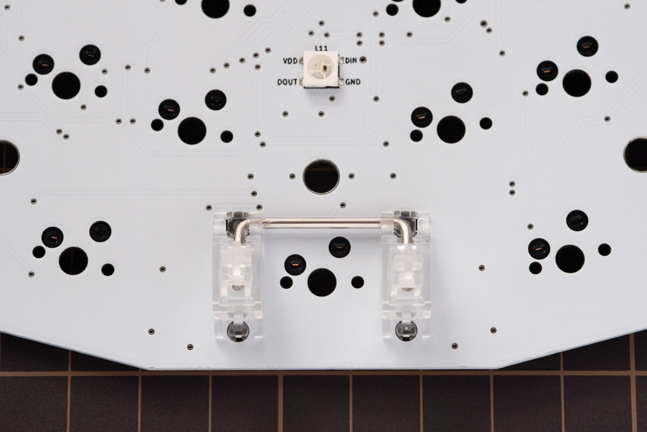
First, there is an LED installation pad marked "L1" on the upper right side of the back of the PCB, so we will attach the LEDs in order from here.
*In PCB ver1.2, the letter "1" of L1 is hidden by a via (hole), but please refer to the position of the photo.
*In PCB ver1.4 and later, all LEDs are placed in the same direction. The orientation is different from the photo. Please follow the silk printed on the PCB.
The LEDs on the back of the PCB are attached in clockwise order from "L1" to "L10". "L11" is in the center of the surface and will be soldered last. Note that the directions of the LEDs are different for [L1/L2/L9/L10 on the top of the PCB], [L3/L8 on the middle], and [L4/L5/L6/L7 on the bottom].
-
Apply flux to the pads on the backside of the PCB.
-
Next, pre-solder only one of the four pads.
If you are right-handed, pre-soldering the lower right pad will make the work easier.)
Put a little solder on the warmed "tip" and apply it to the pad. If you have applied too much, apply a dry (wiped off the solder) soldering iron to the solder piled up on the pad, and the excess solder will move to the tip of the soldering iron.
-
Apply flux to the preliminary solder.
-
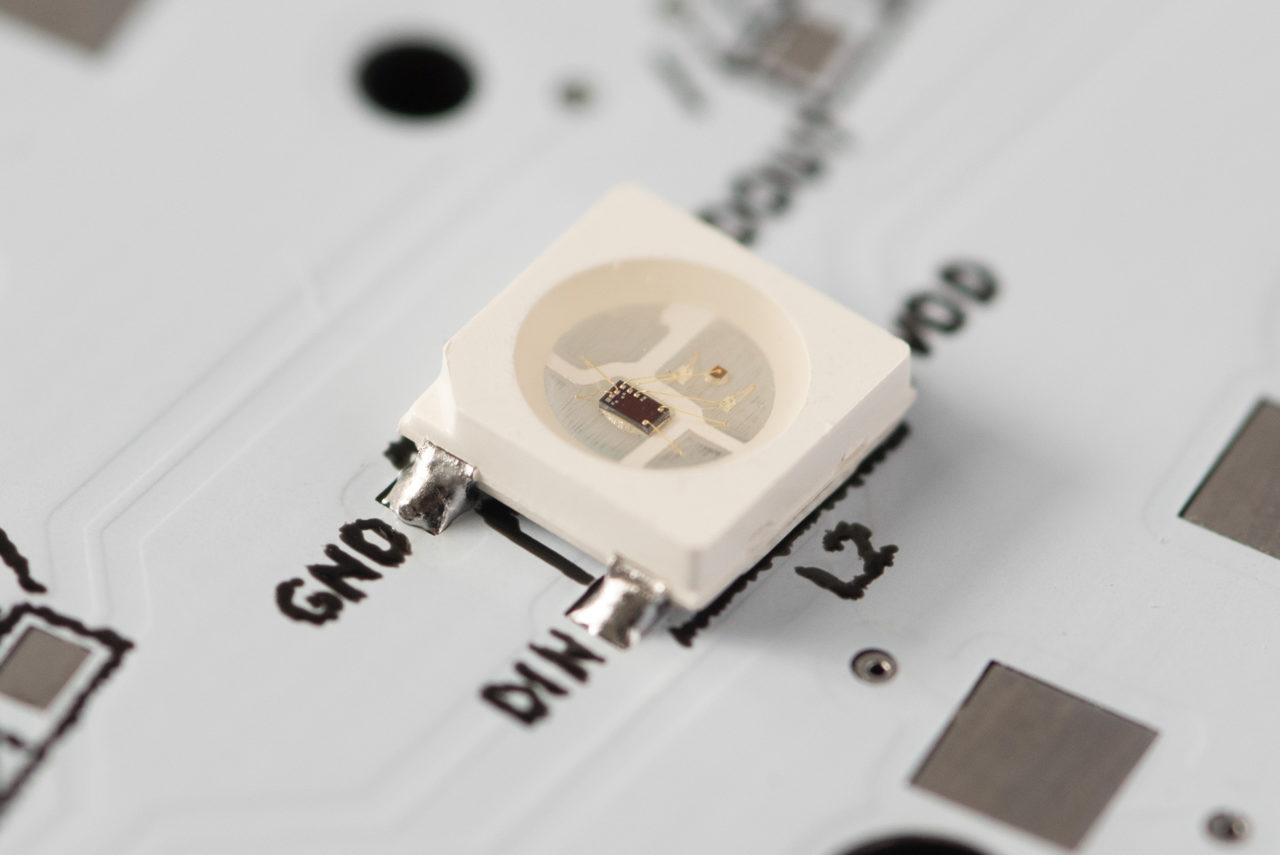
Align and place the LED (WS2812B) using tweezers so that the GND mark on the PCB and the VSS of the LED are aligned. (Place it so that the GND ▲ mark on the PCB matches the position where the △ of the LED is missing.)
- While holding the LED in place with tweezers, apply the soldering iron to the spare solder that you just made and fix the LED.
At this time, work for 2 to 3 seconds so as not to apply the soldering iron too much. Also, be careful not to touch the LED body with the tip of the soldering iron.
Look at the PCB from the side and check if the LED contacts are floating. It is a success if the contact of the LED is exactly on the PCB and fixed.
If the position of the LED is misaligned from the four corner marks (silk/print), or if it is not fixed well, wait until the LED cools down and then recover it.
- Next, solder other pads and LEDs.
Put a small amount of solder on the "trowel" and apply solder to the pad. Also at this time, work for about 2 seconds so as not to apply the soldering iron too much.
As an image, instead of applying solder to both sides of the LED and fixing it, it will be an image that the solder is soaked into the pad of the PCB and the pad surface of the LED (as if sending it thinly).
- Be careful not to float the LED due to the thickness of the solder.
Once you've attached one, wait for the LED to cool down, then move on to soldering the next pad.
After soldering the four points, clean the flux with a flux cleaner.
After soldering the LED of "L1", connect the ProMicro and PC with a USB cable and check if the LED lights up. If it lights up, it's a success.
If it doesn't light up, it could be one of the following:
bad soldering out of position Broken LED Forgot to write firmware
When recovering, be sure to remove the USB from the PC before working.
In the case of poor soldering, it may be difficult to see visually. Try reheating the solder attached to the LED and pad. After reapplying flux to the four solder points on the LED that does not glow, apply the soldering iron to each point for about 2 seconds to remelt the solder. After working one place, wait for the LED to cool down and reheat the solder on the next pad in the same way.
If the LED is misaligned or floating, don't panic and recover the soldering. Apply flux again and work for 1-2 seconds without applying too much soldering iron.
If the LED is damaged, absorb the solder with a solder wick, then use a soldering iron set at about 320° to heat the LED from the sides while carefully peeling it off with tweezers. At this time, if the LED is pulled strongly upward, the pad may come off. Slide the LED sideways with a soldering iron and tweezers or lead pliers, or carefully destroy the LED and remove it from the PCB so as not to damage the PCB.
When the "L1" LED comes on, next work on the "L2" LED to check if it lights up, and then work in numerical order until "L11". (L11 is on the surface)
Be sure to disconnect the USB before soldering. There is a risk of short circuit.
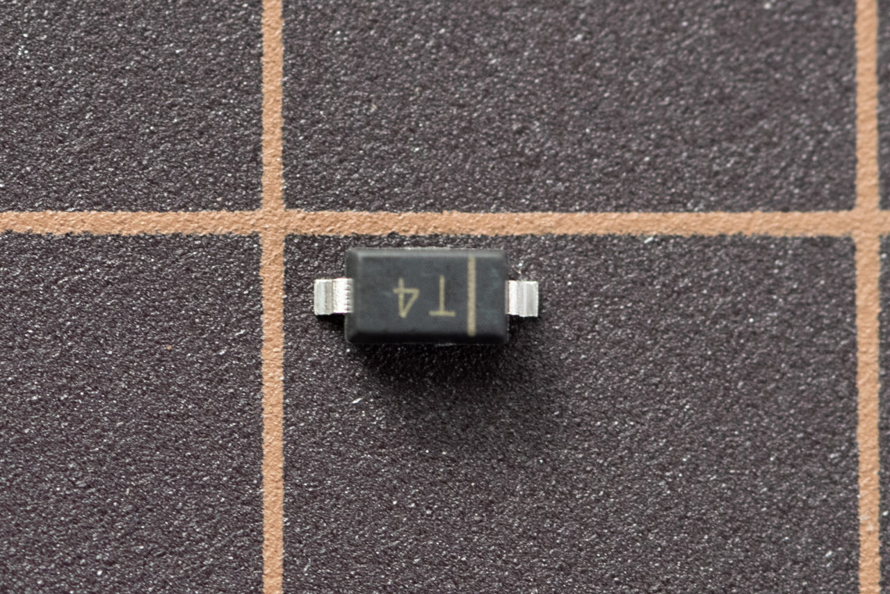
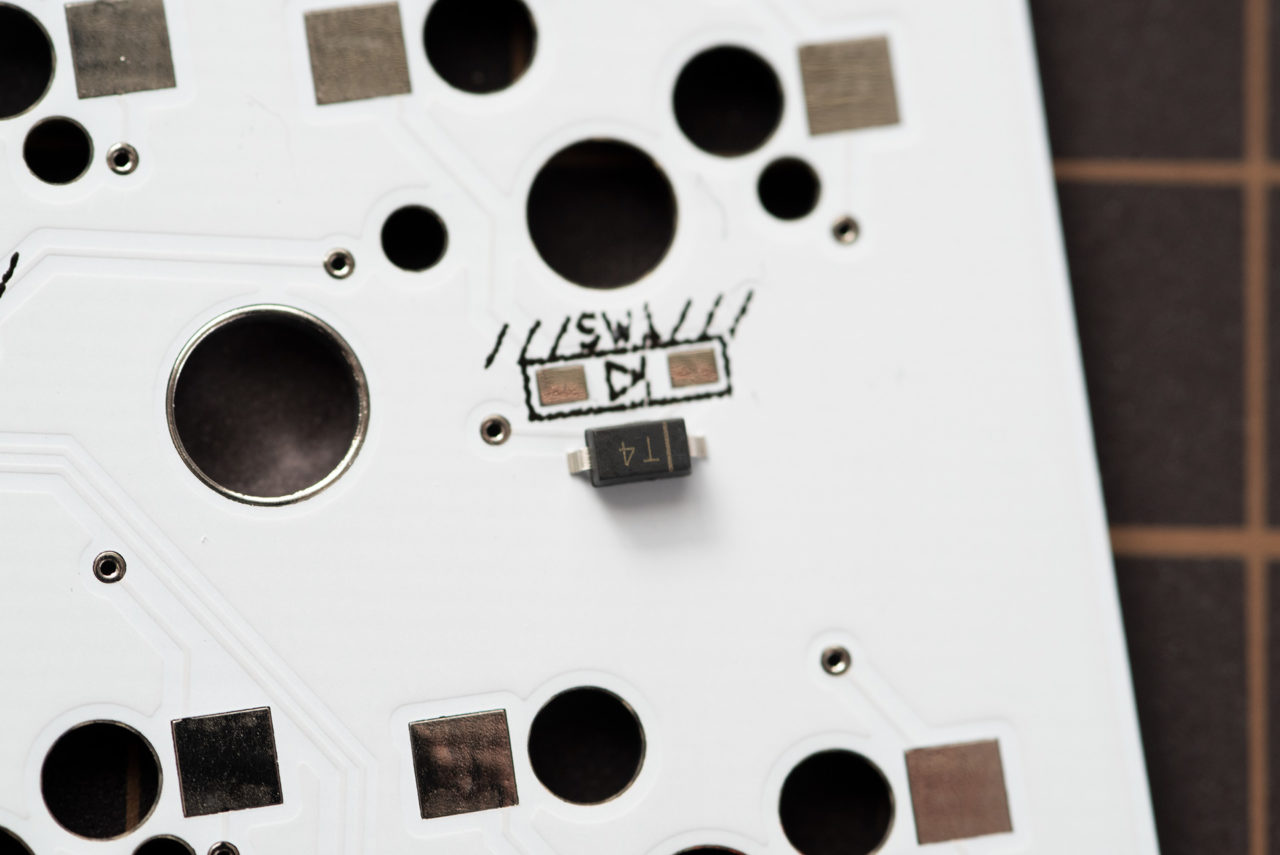
Soldering the diodes
There is a diode mounting position above the switch mounting position, so solder 41 points.
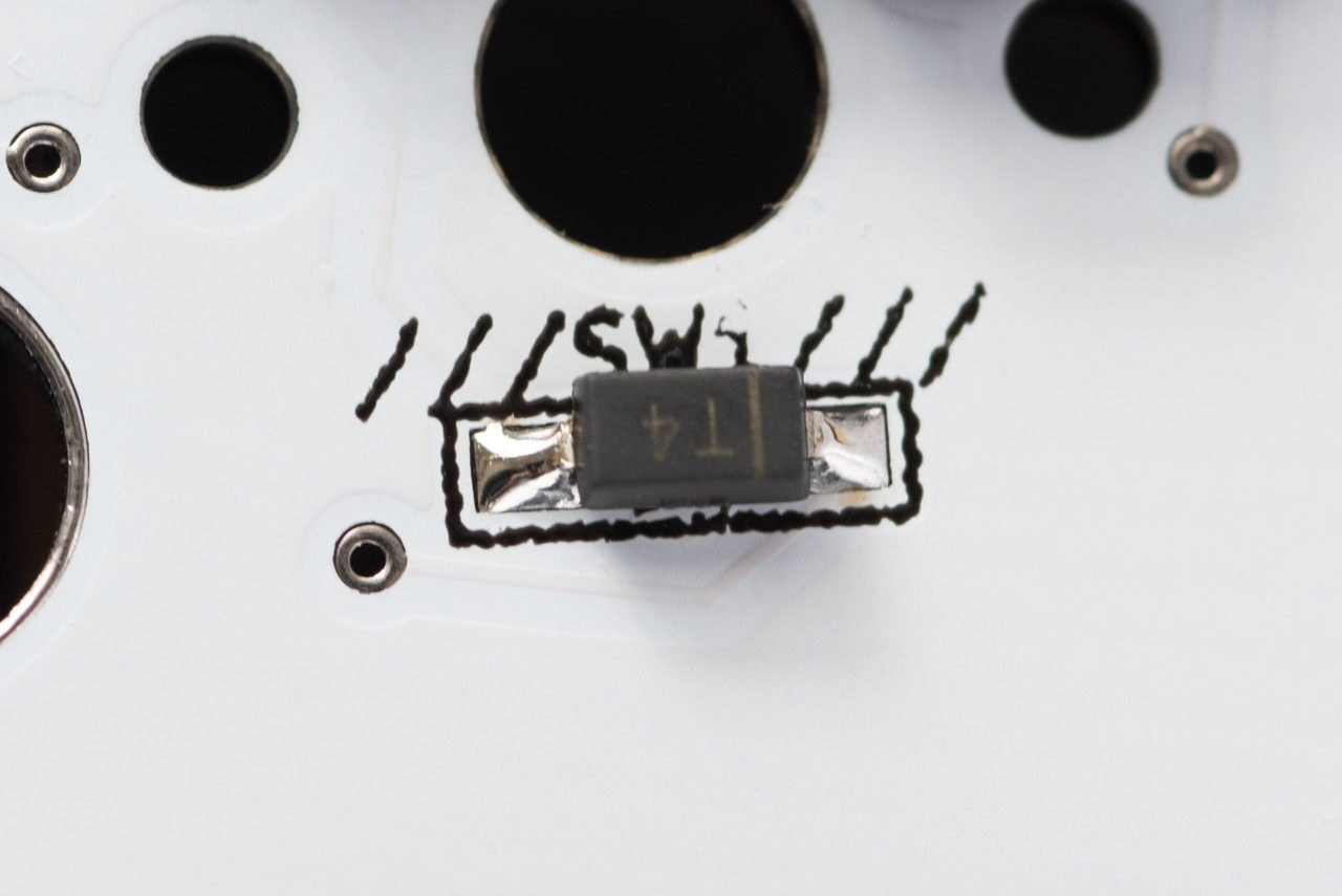
The mounting direction of the diode is fixed. Mount the diode so that the "|" mark on the chip part faces the "|" side of the diode mark "▹|" on the PCB.
Solder while paying attention to the mounting direction. The temperature of the soldering iron is about 320°. A small amount of solder is sufficient.
-
Flux the pads (both) first.
-
Next, apply preliminary solder to one of the pads.
If your dominant hand is right-handed, it may be easier to work from the right pad.
- Use tweezers to align and place the diode.
While holding the diode with tweezers so that it does not shift, apply the soldering iron to the preliminary soldering to fix the diode. Look at the PCB from the side to see if the diode is floating.
Four. Then solder the other side.
After soldering, remove the flux with a flux cleaning solution.
Solder the Hotswap sockets for the switches
Solder 41 sockets for switch connection.
-
Apply flux to the pad and insert the socket. *Sockets also have mounting directions. If you attach it in the opposite direction, it will block the hole in the center of the switch, so please be careful of the orientation.
-
Solder the terminals on one side.
Have tweezers handy as you will need to switch from "thread solder" to tweezers on the way.
Place a trowel on the socket terminal and the edge of the pad and heat for 2-3 seconds. Next, apply "thread solder" from the inside of the terminal to the vicinity of the iron tip, and melt the appropriate amount (small amount) of solder.
Once the solder has permeated the pad surface, remove the solder wire (with the soldering iron still applied), switch to the tweezers, and release the soldering iron while holding the socket so that it does not float .
The amount of solder is small enough to penetrate the four corners of the pad (on the PCB side). You don't need to use a lot of solder.
- Make sure the socket is not floating before soldering the terminals on the other side.
Four. After soldering, clean the flux with a flux cleaner 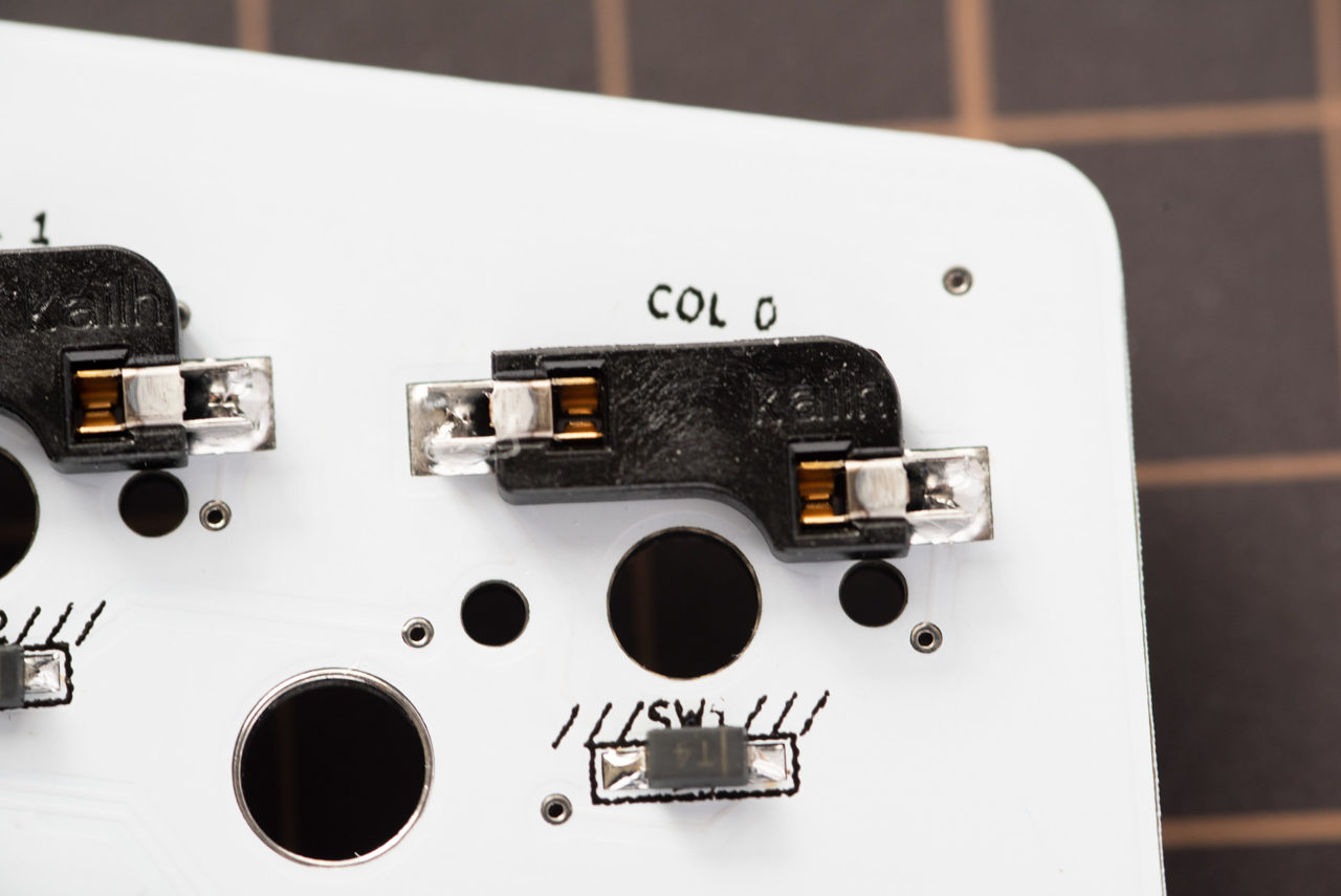 This completes the soldering work. Check the whole to make sure there are no
soldering omissions or incorrect component installation directions.
This completes the soldering work. Check the whole to make sure there are no
soldering omissions or incorrect component installation directions.
Finally, clean the remaining flux with a flux cleaning solution.
Attach the stabilizer to the main PCB.
Attach the stabilizer to the PCB surface. Install the stabilizer so that the shaft of the stabilizer faces upward, referring to the photo.
After installation, check from the side and back that the claws of the stabilizer are firmly attached. *If the nail does not fit tightly, it will not fit perfectly on the top plate.
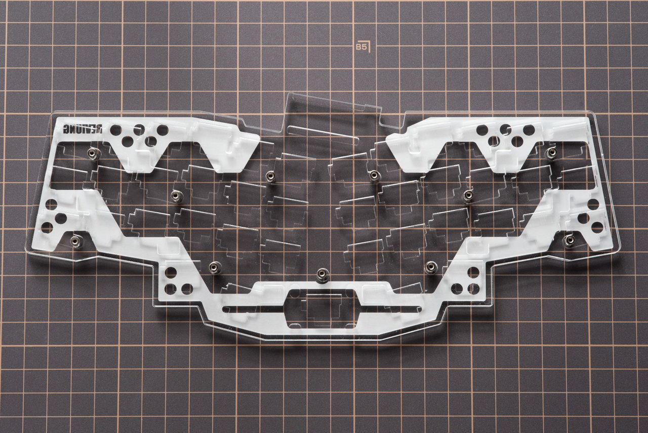
Attach the ProMicro protective cover to the top plate
Attach the ProMicro protective cover to the top plate. (not required)
NOTE *Tightening the screws too much may crack the acrylic parts. Tighten them properly.
*A protective sheet is attached to the acrylic parts. Peel off the protective sheet before assembling.
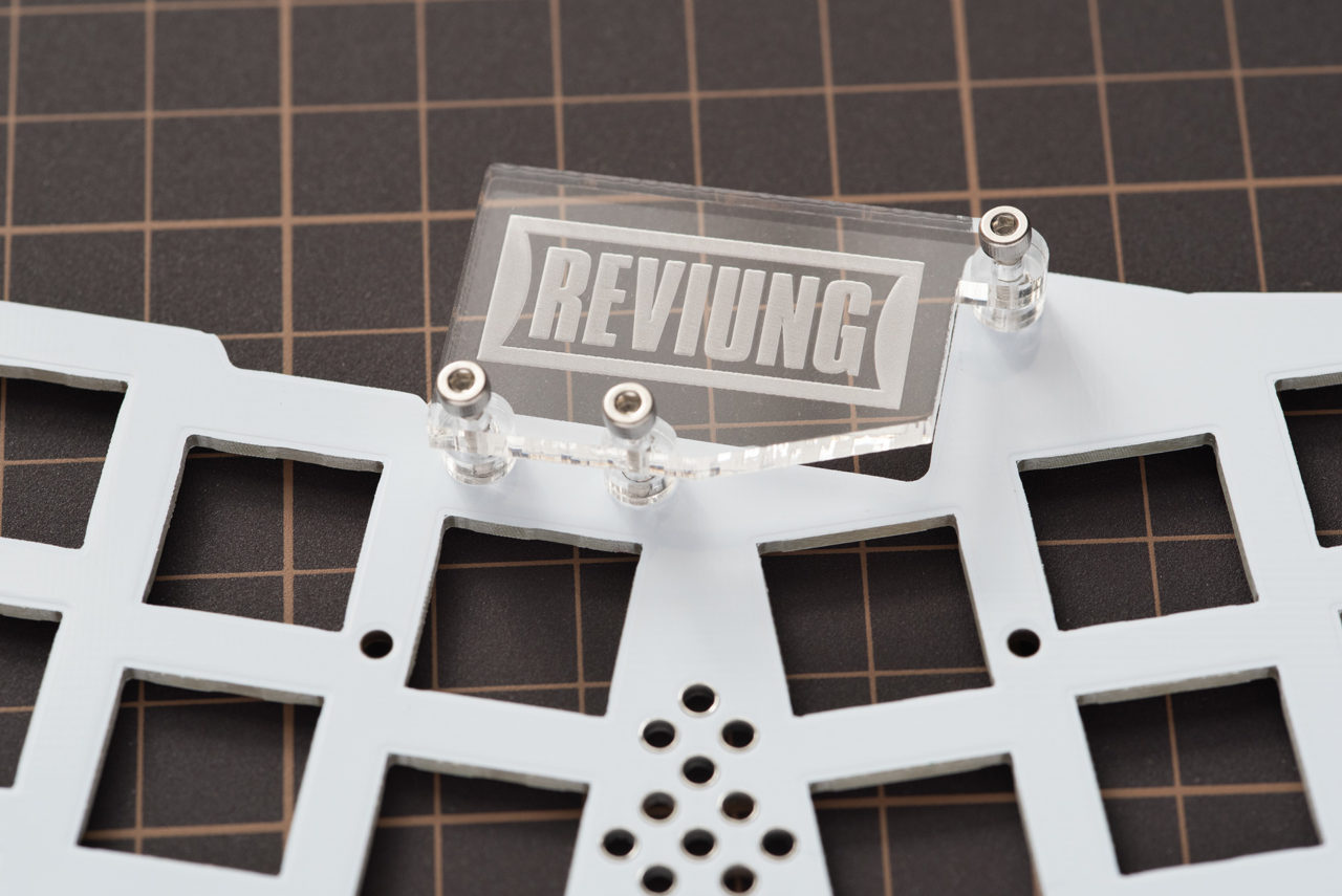
Place the spacer in the screw hole for the ProMicro protective cover in the top center of the top plate.
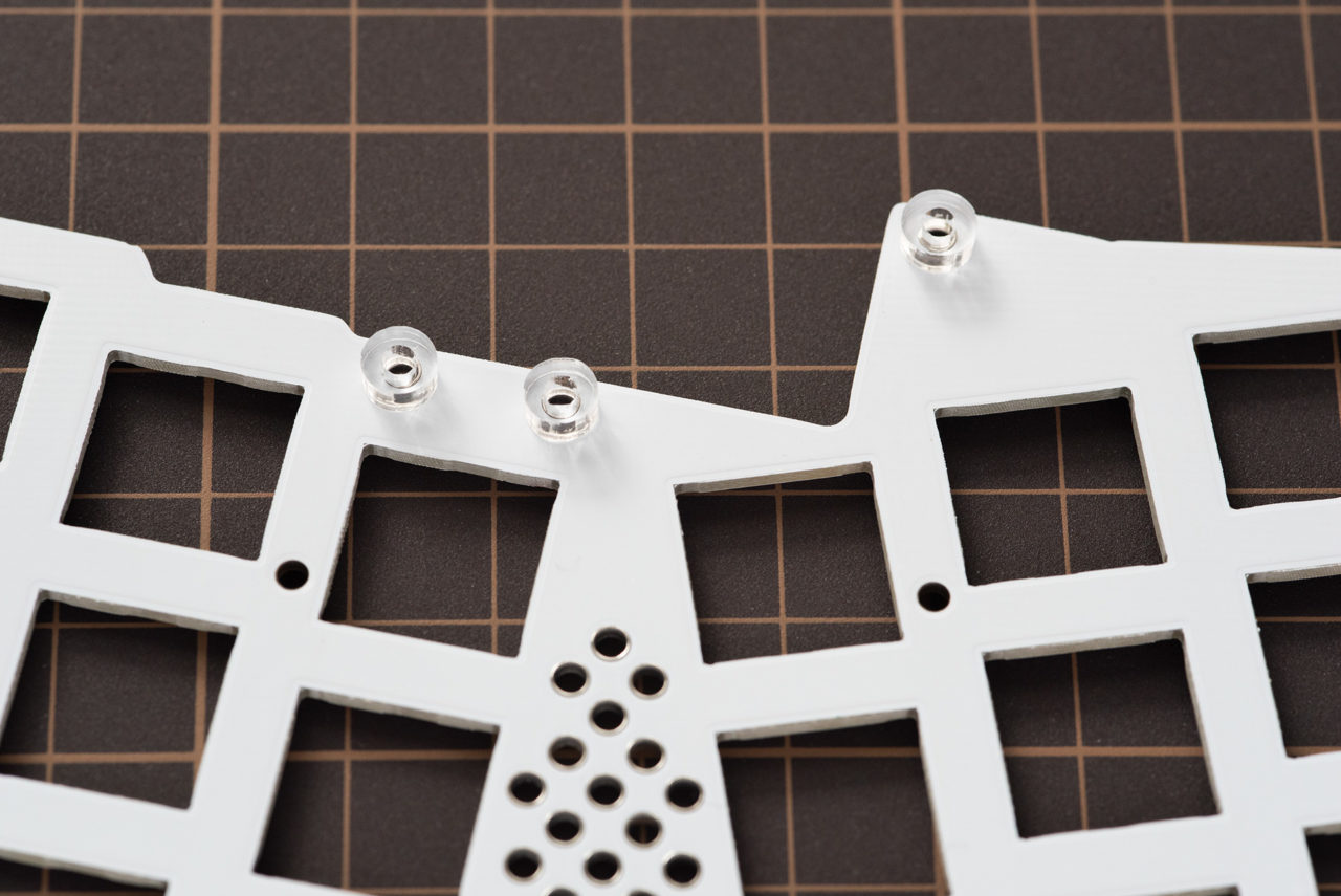
Align the screw holes with the spacers on the protective cover and insert the screws. Secure with nuts from the back side.
Attach the top plate, [option] middle plate (top and bottom), and bottom plate.
Without middle plate
- Fit the switch in the four corners of the top plate and the position of the thumb center key.
- Firmly fit the four corners and middle thumb key switches into the main PCB sockets.
- Engage all remaining switches.
- Attach screws and spacers to the bottom plate, paying attention to the front and back of the bottom plate.
- Place the top plate + main PCB on top of the bottom plate and screw it on to complete.
[Option] When using the middle plate and silicon sheet
-
Paying attention to the front and back of the bottom plate, attach the screws and spacers.
-
[Optional] Place the middle plate (bottom) on top of the bottom plate.
- [Optional] Place the PCB on top of the middle plate (bottom).
- Place the top plate ([option] silicon sheet + middle plate (upper)) on the PCB and screw the spacers to complete.
Finally, attach the rubber feet to the four corners of the bottom plate and just below the screws above the space bar position. (5 locations in total)
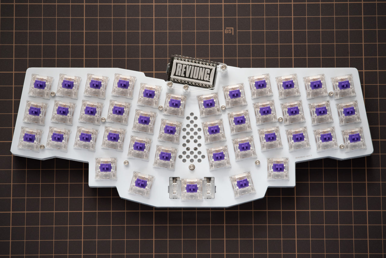
Install the switch.
nsert the switch into the socket from the top plate side. Check that the switch terminals are straight and straighten any bent ones before inserting them into the sockets.
If the switch is 5-pin, it may be tight (hard) to fit. It was tough with Gateron ink Black (5pin). A 3-pin switch can be attached smoothly.
The switches I tried were hard to fit in the following order. 3-pin switch << Turquoise Tealios, Zealios < Gateron ink Black
If the switch is hard and does not fit easily, place your thumbs on top of each other and push it in firmly. Putting a cloth such as a towel between the switch and your thumb will make it easier to apply force so that your fingers do not hurt.
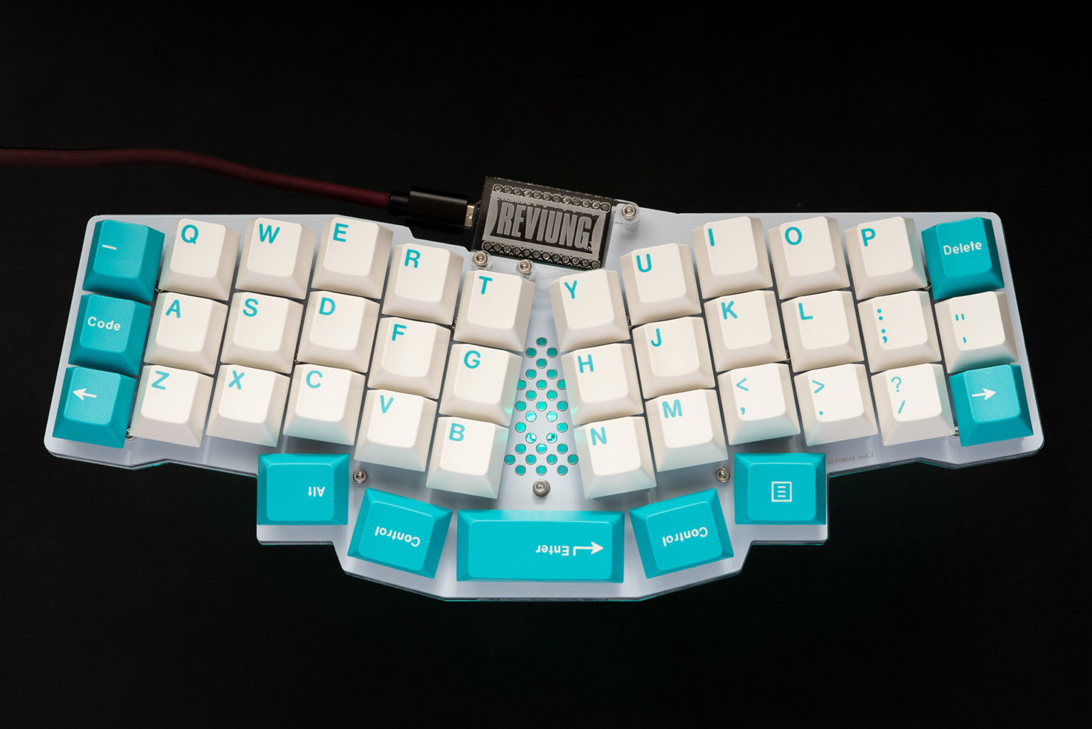
Attach the keycap and you are done.
Finally, attach the keycap and you are done. Attach the keycap of your choice.
The bottom 5 keys are available with the following size keycaps:
| space bar | 2.25U | or 2U |
|---|---|---|
| 4 right and left | 1.25U | or 1U |
That's all.
good job for today.
Firmware
QMK
In qmk this keyboard can be found under QMKKEYBOARDNAME. #TODO To begin, follow the QMK setup guide. (if working from an existing installation, an update may be needed.) \ For flashing instructions, see doc or video
KMK / PEG
In Peg or KMK this keyboard can be found under KMKKEYBOARDNAME #TODO
Peg can be downloaded here, and the quick start can be seen here.
For Kmk can be downloaded here and the quick start can be seen here
Extra
For questions, ask in Boardsource Discord server