Rhymestone build guide
Parts list

Kit accessories
| name | number | remarks | ---- | ---- | --- | | PCB | 2 sheets | | | Top plate | 2 | The one with many square holes | | Bottom plate | 2 pieces | The one with only screw holes | | OLED/Pro Micro protection plate | 2 sheets | | | OLED Pro Micro Protective Plate for 30 Key Challenge | 2 Pieces | Optional | | M2 spacer 8mm | 12 | | | Plastic spacer 3 mm | 8 pieces | Used in combination with M2 spacer | | M2 screw 5mm | 20 pcs | | | M2 black countersunk screw 4mm| 4 | Screws to attach to the protective plate | | Rubber feet | 8 | 4 large and 4 small | | Diodes | 40 pcs | | | TRRS Jack | 2 pcs | | | Tact switch | 2 |
What you need other than the kit
| name | number | remarks | ---- | ---- | --- | | 3.5mm stereo cable (3 poles) | 1 cable | For connection between keyboards | | MicroUSB cable | 1 cable | For keyboard and PC connection | | Key Switches | 40 | MX Compatible | | Keycaps | 40 pcs | MX Compatible | | Pro Micro | 2 pcs | | Spring pin header 12P | 4 pcs | It's convenient for replacement and checking, so it's highly recommended. | MX Sockets | 40 pcs | Sockets for MX Switches | | SK6812mini | 40 pieces | For backlight (optional) | | OLED module | 1-2 pieces | For OLED (optional) | | Pin socket 4P | 1~2 pieces | For OLED (option) | | Pin header 4P | 1 to 2 pcs | For OLED (option) |
OLED and pin socket for OLED
OLED can be attached to both hands. Since the status for various operation confirmations is displayed on the left hand side, it works well even if you purchase only one side.
If you buy only OLED from AliExpress or Yusha Kobo, there is no pin socket, so please purchase separately from Akizuki Denshi or Hirosu Guinette. There are various types, but the socket
- 2.54mm pitch
- Low profile board mounting height 3.5mm
- pin socket
- 1x4(4P)
"I need something."
SK6812mini
The SK6812mini for the backlight is vulnerable to solder heat, and unless it is a soldering iron with a temperature control function, failures often occur and it takes a long time to damage the parts. Chinese-made soldering irons with a temperature control function are cheap, but depending on the item, the temperature may not be accurate and may damage the parts, so if possible, use temperature-controlled soldering irons from Japanese manufacturers such as HAKKO. Please use Also, the soldering tip (soldering tip) is not the pencil type that comes as standard, but it is recommended to purchase a diagonally cut type separately, as it will make a mess.
Required tools
| Name | Remarks |
|---|---|
| Soldering iron | When installing the backlight LED, one that can adjust the temperature is essential (If the temperature cannot be adjusted, the LED damage rate is quite high) |
| Flux | It's essential if you want to install a backlight LED because it makes a lot of progress |
| Thread solder | About 0.8 mm is recommended |
| Solder wick | For failure |
| Nippers | For cutting diode lead wires, etc. |
| Tweezers | Used for ProMicro resetting and chip LED soldering |
| Flux remover | Although it is not essential, it can remove the stickiness after soldering, and the yellow discoloration caused by solder can be wiped off for a clean finish. |
| Masking tape | Used for marking and temporary fixing. 100-yen pattern is OK |
Mtei's Memo of tools required to make a Helix keyboard kit And hdbx's Tools to prepare when starting your own keyboard will also be helpful.


Preparation of promicro
Please reinforce the promicro connector and solder the through pin. Please install the promicro so that the surface on which it is mounted faces the keyboard board.
- Promicro's connector reinforcement: Write QMK_Firmware while preventing promicro's moge
- Soldering Cons Through Pins: Helix Beta Build Guide

Prepare QMK
This keyboard is programmed to work with keyboard software called QMK. The pre-registered default keymap is actually used by the author, and is devised so that it can be used almost without any inconvenience.
- Install QMK Toolbox from the link below
- Select rhymestone from the list under "Keyboard from qmk.fm" in QMK Toolbox
- (If you can't find it, download the default hex file from the link below and select "Local File")
- Connect the promicro (or the board if it is directly attached) to the PC and
press the reset button to write.
- (Some patterns cannot be written unless the reset button is double-clicked.)
Salicylic Acid's article [(Beginner Edition) Writing firmware to a self-made keyboard] (https://salicylic-acid3.hatenablog.com/entry/qmk-toolbox) will be helpful for how to write.
Customizing the keymap
If you have no programming experience, it would be quicker to use the QMK Configurator.
Create a build environment
If you can build from the source by yourself, you can freely customize each key to detailed operation.
[Prepare the QMK build environment] (https://docs.qmk.fm/#/ja/newbs_getting_started)
The default keymap for rhymestone is qmk compile -kb markard/rhymestone -km default is possible. if you write qmk flash -kb markard/rhymestone -km default Then, as soon as the compilation is completed, it will wait for
writing, so in that state, click the reset button on the board or double-click
to start writing.
About the back and front of the board
The side on which the key switch is mounted and faces upward during normal use is the front, and the reverse is the back.
Determine the left and right sides of the board

The included board is a reversible board that can be used on either the left or right side. In order not to forget the left and right while creating, write left and right on the mask, and decide that the side you pasted is the front (the side where the key switch will be attached).
Solder the diode
bend the legs of the diode
Bend all the legs of the diode before attaching it to the board. Try to find a jig to determine the distance between the holes in the board and bend it. I think it's good to have disposable chopsticks that are still connected.

I was able to use the USB-C to USB-A conversion connector just right, so I bent two or three diodes at once.

Soldering the diode
The mounting direction of the diodes is the same for each board, so if you check one and install it, you can install the rest in the same direction. Install the diode with the black strip side facing the square of the diode mounting hole on the board.


Insert the diode from the back side of the board on the left hand side. After inserting, screw the legs of the diode together to temporarily fix it. You can do it easily and quickly by inserting each horizontal row and soldering them together. After soldering, cut the leg from the base.


Insert each row, solder, and cut repeatedly. Do the same for the right-hand board.

(Optional) Solder the LEDs
We will install a full-color chip LED on the back of the key switch.
LED Mechanism and Connection Order
This chip LED has four terminals (lands), VCC, GND, DIN, and DOUT respectively. Did you do VCC and GND in junior high school? I think that it is good to recognize that each is a battery + and -. DIN and DOUT are lines that control the lighting pattern of the LED. DIN is the input and DOUT is the output. Multiple LEDs are controlled by connecting these DIN and DOUT in a daisy chain.
Regarding the connection order of the Rhymestone, it is wired in a spiral from the outside to the inside, starting from the end where the reset button is installed. It is safer and faster to install a few pieces → check the lighting → install a few pieces, so please install them in this order.

Orient
Install so that the front side of the LED faces the front side of the board. The mounting direction is the same for each board, so if you attach the first one correctly, you can imitate the rest.
left hand side


right hand side


Pinch the chip LED with tweezers with your left hand and insert it into the hole of the PCB for alignment

Apply flux with your right hand while pinching
I didn't pinch it in the photo, but please apply flux while pinching it and move on to the next step.

Add some solder to the tip of the soldering iron set at around 220 degrees
Please set the iron tip to around 220 degrees. 270 degrees is high. "Put some solder on the soldering iron." The lands are connected by rubbing them against the lands with a feeling of piling up a little solder. First attach one of the four lands so that the land of the board and the land of the chip LED are as horizontal as possible. Once attached, release the tweezers and attach the remaining three in the same way.

Check LED lighting
I think that the firmware for checking LED operation has been written to the pro micro in advance, so please attach the pro micro by aligning the pin with the white frame on the front of the board (the side where the mask is pasted). "If you install it, the LED will light up." If it lights up, VCC, GND, and VIN of the four pins are properly soldered. If it doesn't light up, the main cause is that the VCC, GND, and VIN solders on the LED you just attached aren't properly soldered, or the VOUT solder you attached one before isn't soldered properly.
Solder the remaining lands in the same way
"After that, repeat this to add 20 on one hand and a total of 40 on both hands." I'm pretty happy that I can check the progress from time to time, and it's easy to understand where and what happened when the light doesn't turn on, so please do it steadily.
After everything is installed, the soldered area will become sticky with flux, so if you are concerned about it, wipe it off with a flux remover.


(Optional) Installing OLED
PCB land short for OLED mounting
On the front side of the board, I think there are 4 sets of 8 small ■ on the bottom side where the Pro Micro is attached. Short-circuit each pair with solder. The trick is to apply flux to the soldering surface of the board, put a small amount of solder on the soldering iron, apply it to the board, and remove it from the board after applying it for about 4-7 seconds. If it doesn't stick, remove the solder on the soldering iron and try again.

Soldering the pin socket/pin header for OLED
In order to install it straight and easily, temporarily hold it with masking tape so that it sticks straight, then flip it over and solder it.
Solder the TRRS connector, tact switch
In order to install it straight and easily, temporarily hold it with masking tape so that it sticks straight, then flip it over and solder it. The tactile switch snaps into place, turns over and solders.

Snap the switch into the top plate
You can solder the sockets first, but it's quicker and cleaner to fit the switches into the top plate first and then solder them after inserting the sockets into the terminals. Please fit your favorite switch into the top plate.

Solder the MX socket
First, align the top plate and PCB. Align the central protrusion on the back of the switch with the hole in the PCB and attach it.

Mount the MX socket by aligning it with the white mark on the silk of the PCB. Make sure that the switch pins are properly inserted into the MX sockets, and snap them all together.

"The rest is soldering." If you install an MX socket, you can replace the switch. There is no point in just piling it up thickly, so let the solder flow firmly between the PCB and the socket. Add a generous amount of solder to the tip of the soldering iron, and pour the heat into the socket as if you were attaching it to the PCB that you can see in the gap between the metal fittings of the socket.
Spacer installation
Peel off one side of the bottom plate's protective paper, and attach the rubber feet to the removed side. A large one and a small one are included so that they can be tilted as standard, so attach the two smaller ones to the front and the two larger ones to the back.

Remove the rest of the protective paper and use four 8mm spacers and four 5mm screws to screw it to the bottom plate. After screwing, insert the 3mm resin spacer into the 8mm spacer. This resin spacer works to prevent the PCB from sinking when replacing the switch.

Mounting the protection panel
Install a blindfold around the Pro Micro and a plate to protect the OLED. Attach two 8mm spacers to the PCB (yellow ○ in the photo) with 5mm screws. Remove both protective papers from the plate and attach it to the spacer attached to the PCB with a black 4mm screw. There is a little play, so if it interferes with the keycap when attached, please shift it slightly.

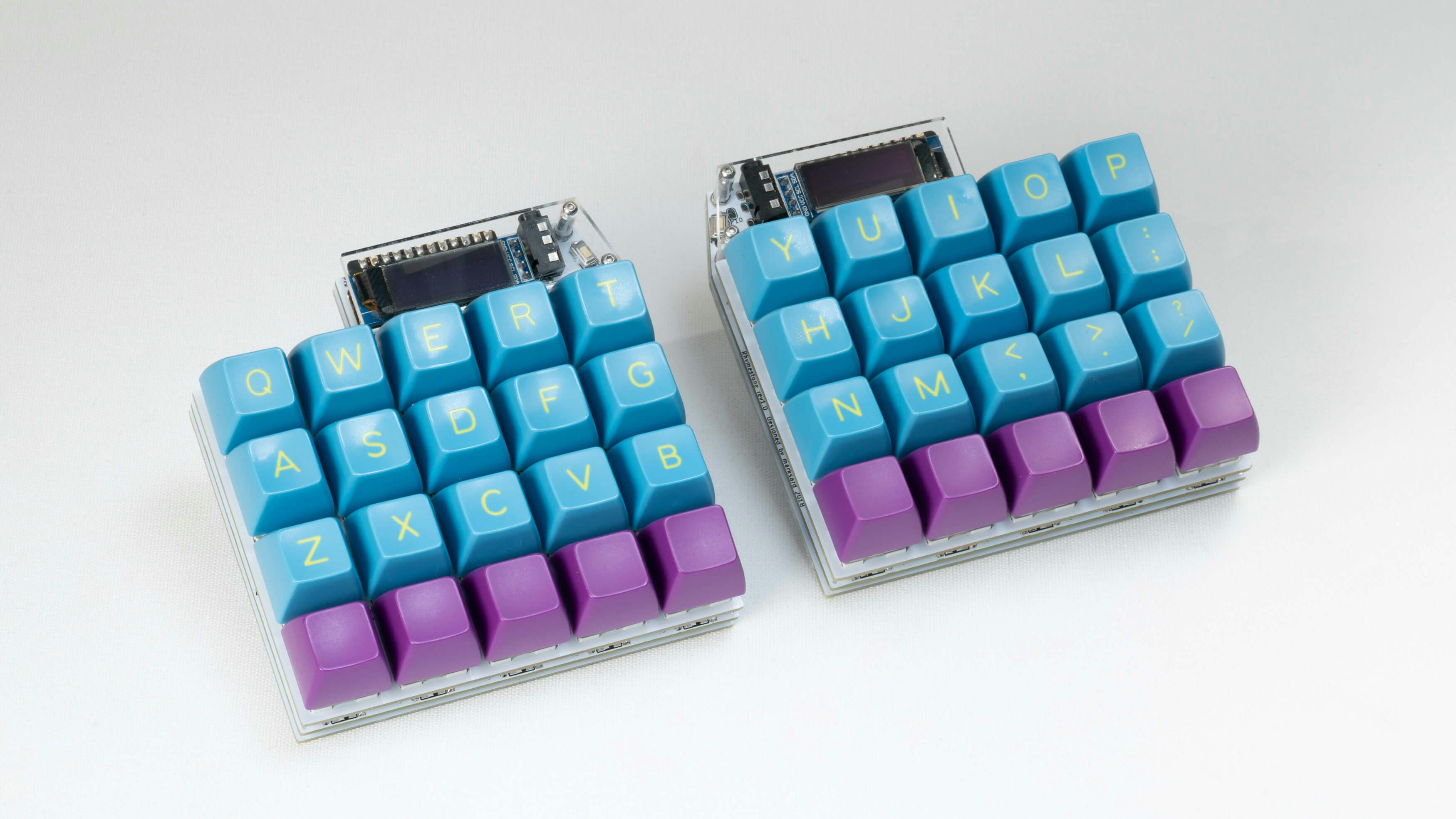
Installing keycaps
"Attach your favorite key cap."
Flash keyboard firmware
For those who wrote led_test for testing the LED backlight, please go back and write the default keymap.
test
"First, connect one to the PC and test." If you attach one at a time, it will always be recognized with your left hand, so please check if the keys are recognized with a keyboard tester app. If you have an OLED installed, the 4th line of the OLED is the switch status. It's OK if something changes.
"Remove ProMicro and USB." Connect the left and right with a TRRS cable, connect the ProMicro and USB on the left hand side, and let the PC recognize it. "Please check if communication is possible on the left and right."
Complete!
"If everything looks fine after checking, you're done!" Please finish it to one only for you!

How to replace the keyswitch
Since it is difficult to remove by hand, please use a key switch extraction tool sold on amazon etc. to replace it.
How to use OLED Pro Micro protection plate for 30 key challenge
Remove the top row of key switches, remove the normal protective plate, and
install the protective plate for the 30-key challenge. The explanation about
the keymap is
here
 "At first, I'm not sure where my thumb is, but once you get used to it, it's
fun!" Please try the challenge.
"At first, I'm not sure where my thumb is, but once you get used to it, it's
fun!" Please try the challenge.
troubleshooting
Please refer to the Troubleshooting page.
Firmware
QMK
In qmk this keyboard can be found under QMKKEYBOARDNAME. #TODO To begin, follow the QMK setup guide. (if working from an existing installation, an update may be needed.) \ For flashing instructions, see doc or video
KMK / PEG
In Peg or KMK this keyboard can be found under KMKKEYBOARDNAME #TODO
Peg can be downloaded here, and the quick start can be seen here.
For Kmk can be downloaded here and the quick start can be seen here
Extra
For questions, ask in Boardsource Discord server