Overview
This build guide walks you through how to build the Stress wasd fight pad.

Kit Contents
- PCB
- FR4 Backplate
- FR4 Plate
- rp2040 zero controller
- start select switches
- Hotswap Sockets (optional)
- choc switches & keycaps
- Standoffs
- M2 Screws
- Rubber Feet
Soldering
Hotswap sockets
- Solder one pad.

- While holding hotswap socket (fingers are fine), reflow solder and place
socket down on pad.

- Solder other pad.


- Note, don't hesitate to use a little extra solder, as that will help secure the socket and prevent it from being ripped off.
Tact Switches
- install your tact switch on the top side (opposite of the hotswaps)


- solder the back of your tact switch


Controller
Place your controller on the top side of the pcb (opposite of the hotswaps) and line up the holes in the pcb.
tip: it can be helpful to use some of the pins included with the controller to line up the contrler but we DO NOT solder the pins into the pcb.

once you have lined up the controller solder in one conner to lock it in place


After that you can continue around the controller and solder the rest of the pins.

Final Assembly
Note: Be careful when using the threaded standoffs and M2 screws to not force anything in to place. They are very easy to strip. Do not over tighten.
Connect Standoffs to the Backplate
The first step of final assembly is to connect 4 threaded standoffs to the back plate
Install Switches Into Plate
Install a switch into each of the switch holes on the plate.
Sandwich the Plate onto the PCB
In order for final assembly to take place, we must marry the switches, switch plate, and PCB together.
Bring the pieces together and line up the switch legs with the holes on the hotswap sockets. Firmly but carefully apply pressure as evenly as possible to press the switch legs into he hotswap sockets. Do small sections at a time and do not press down the entire way, keep doing this around the board until all areas are pressed down entirely.
It is possible to accidentally bend a switch leg, and that is okay, usually you can just remove the plate from the PCB and un-bend the switch leg and then try again. It happens to everyone.
Secure the Plate and PCB to the Backplate
Now we can make use of those threaded standoffs we installed on the backplate. Place the plate_PCB assembly into place lining up the holes, and secure the plate_PCB assembly to the backplate’s threaded standoffs using the included screws through the plate. Do not over tighten.
Install Keycaps
Install any keycap of your choosing onto the switches.
All Done!

Flashing.
Downloads
This kit uses the awesome gp2040-ce gamepad firmware
Download the files below.
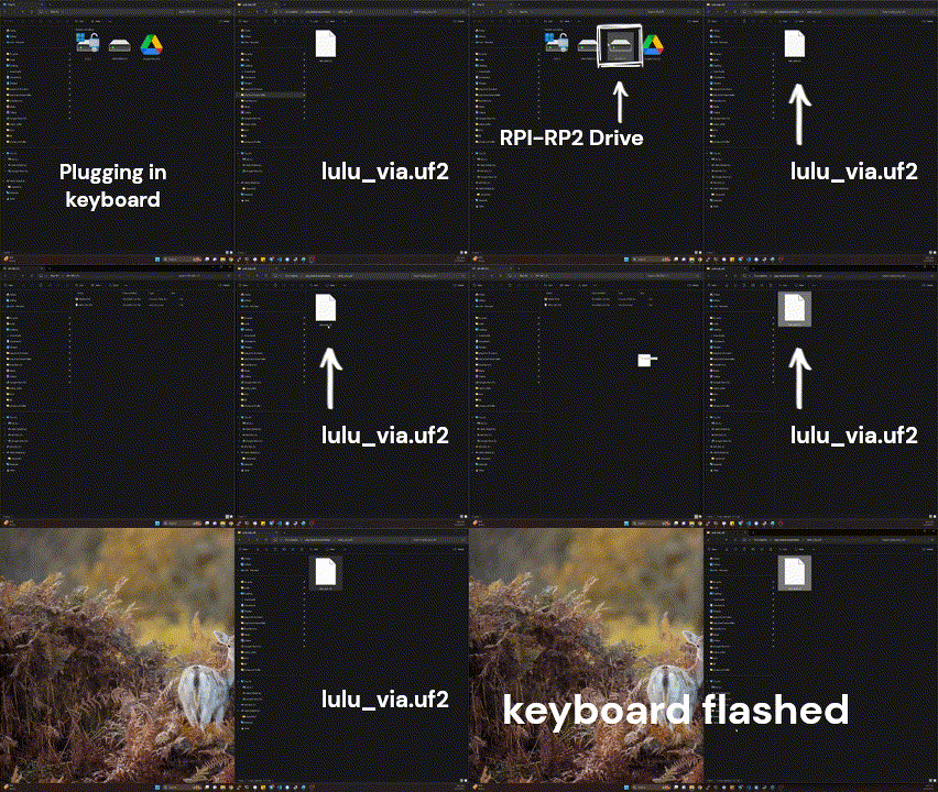
Once you have the files downloaded we need to flash the firmware. To do so you need to hold down the boot button on the blue controller in the center, while you plug in the controller to your computer.
After you do that it will show up as a drive and you can transfer the .uf2 file you downloaded from the first link.

After your fight stick is flashed you can then open the web config by holding down K1 and plugging in your fight stick again.
and follow this link
That should open the web config, head over to Configuration>Data Backup and Restoration on that page you can go to the Restore From File section and click the load button and you can select the second file you downloaded. This will set up the controller for normal fighting games.
