Build Guide
Alrighty, so you got your tg4x stuff, but don’t know how to put it together.
I’ve finally gotten around to making this build guide, so now you’re covered.
Inside your box (depending on what you ordered), you should have 2 packages.
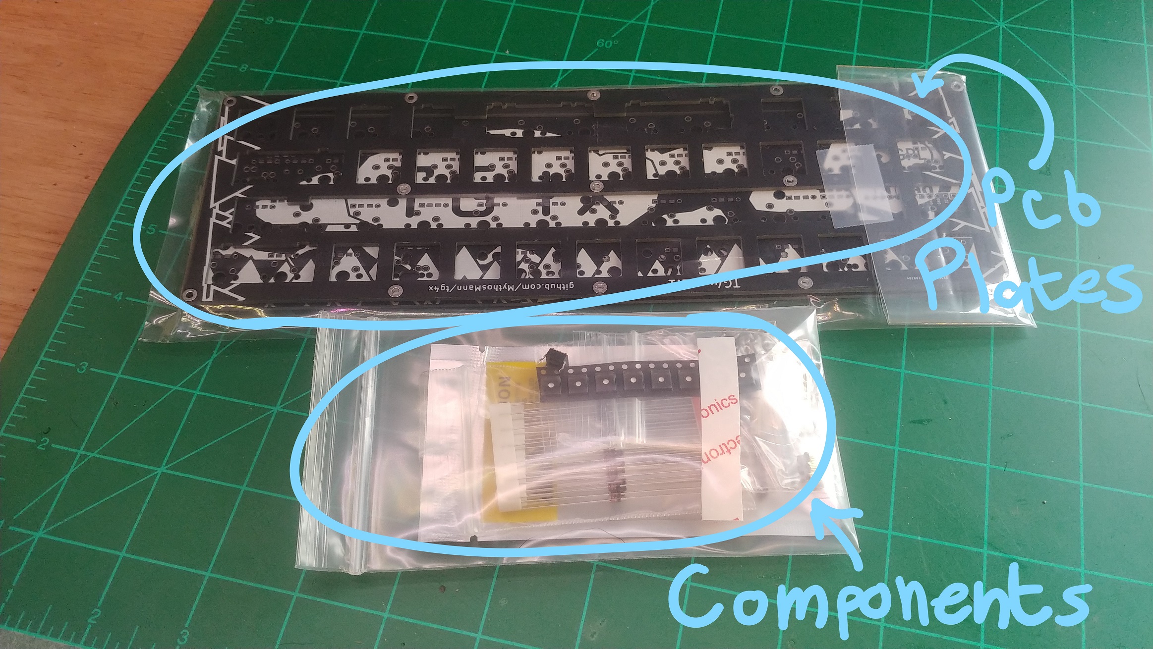 One bag is the plates, and the pcb. The other is your assembly kit, which
contains all of the other pieces and components you need.
One bag is the plates, and the pcb. The other is your assembly kit, which
contains all of the other pieces and components you need.
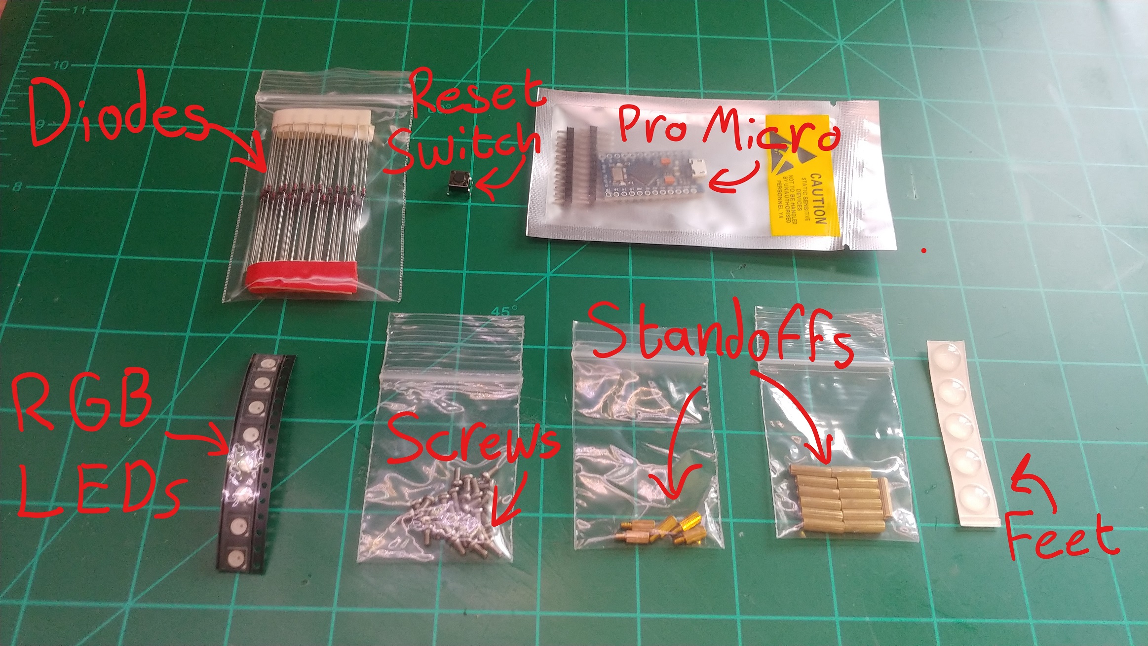 Inside your assembly kit, you’ll find 50x diodes, a reset switch, a pro micro,
8x ws2812b rgb leds, ~28x screws, 5x 5mm male/female standoffs, 13x 11mm
female/female standoffs, and some little rubber feet.
Inside your assembly kit, you’ll find 50x diodes, a reset switch, a pro micro,
8x ws2812b rgb leds, ~28x screws, 5x 5mm male/female standoffs, 13x 11mm
female/female standoffs, and some little rubber feet.
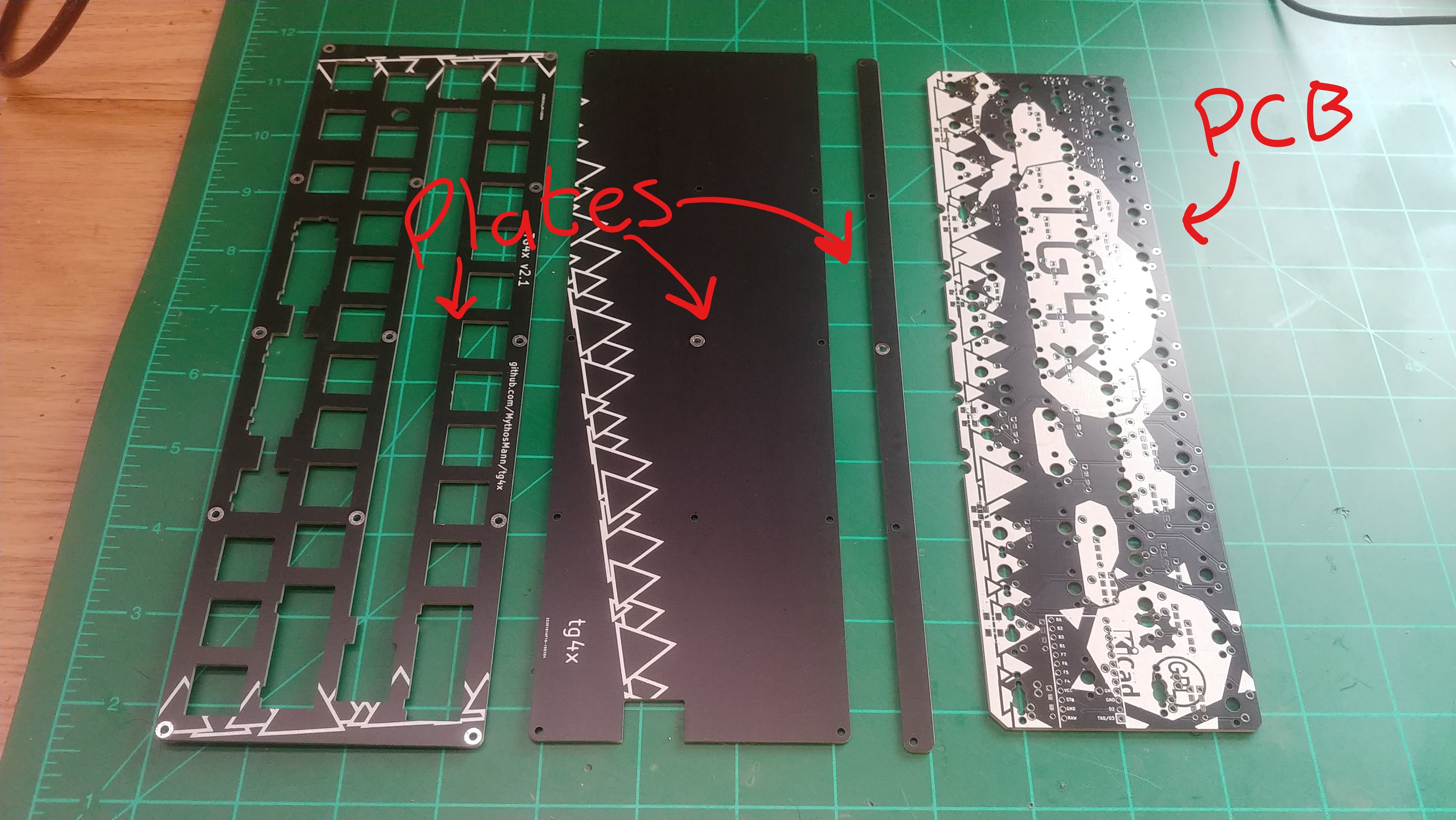 In the other package, you’ll get a top plate, bottom plate, and a skinny little
plate that you can use as a foot (to add a ~5 typing angle). You’ll also get the
pcb, where the magic happens.
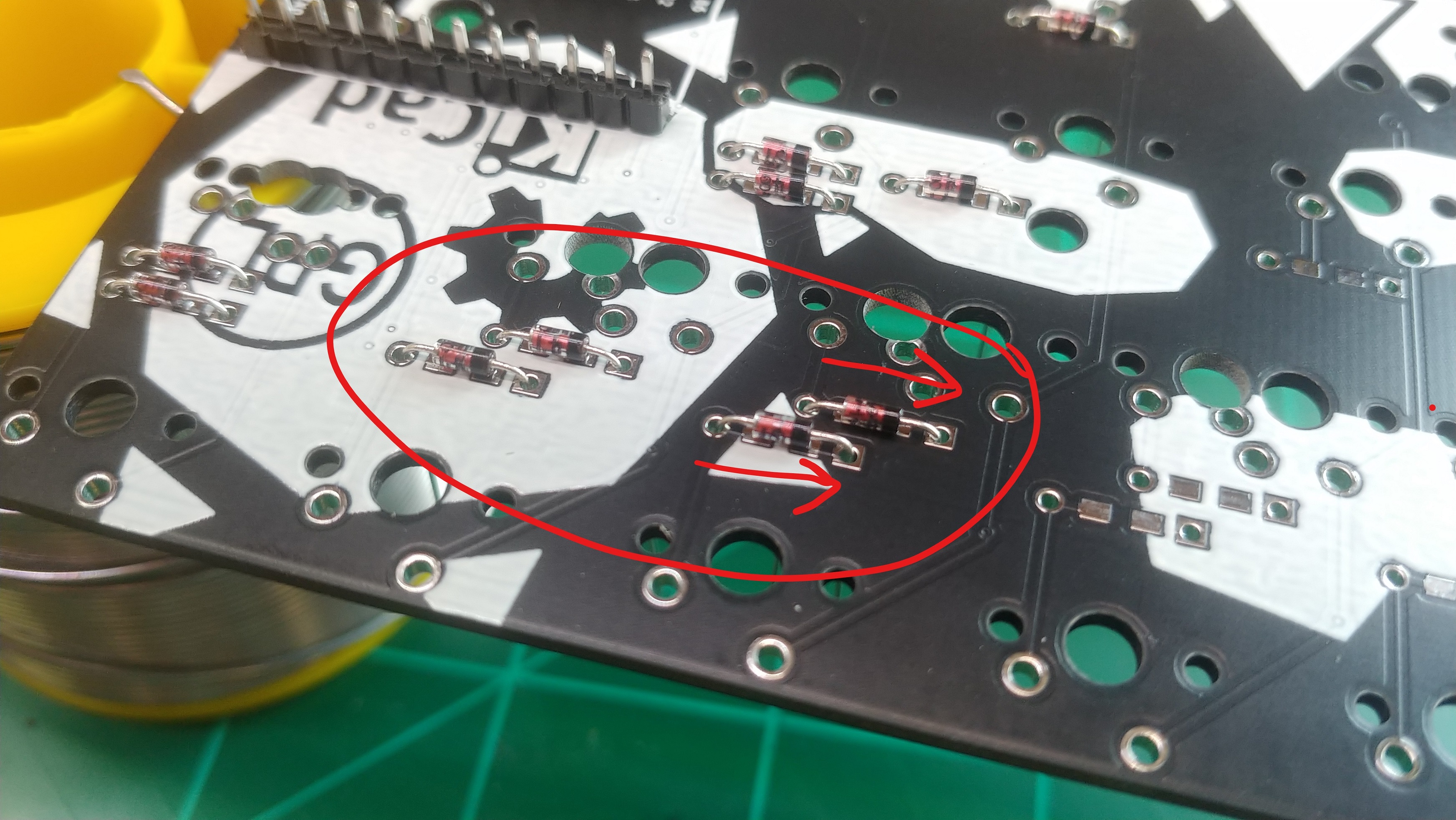
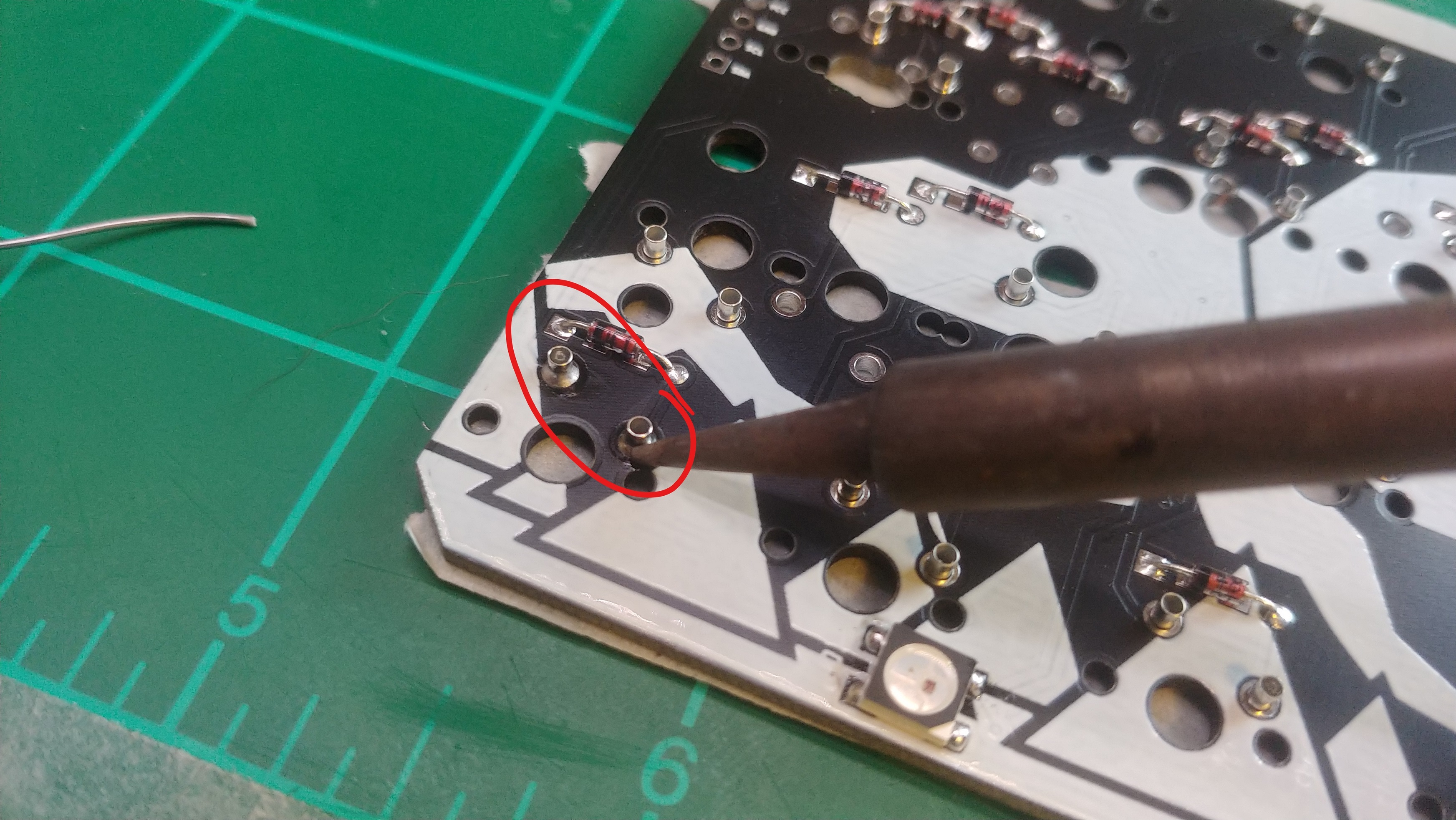
First thing you’ll want to do is bend all your diodes. An easy way to do it
consistently is to use your plates and pcb, put the diodes on top, and push all
the legs down. Then you’ve got to pull the paper off all the leads. Next, you’re
gonna put diodes in all of the diode holes. It doesn’t matter if you put them on
the top or bottom of the pcb, but make sure that they are oriented correctly.
You want the end with the black strip to go into the square holes.
In the other package, you’ll get a top plate, bottom plate, and a skinny little
plate that you can use as a foot (to add a ~5 typing angle). You’ll also get the
pcb, where the magic happens.
First thing you’ll want to do is bend all your diodes. An easy way to do it
consistently is to use your plates and pcb, put the diodes on top, and push all
the legs down. Then you’ve got to pull the paper off all the leads. Next, you’re
gonna put diodes in all of the diode holes. It doesn’t matter if you put them on
the top or bottom of the pcb, but make sure that they are oriented correctly.
You want the end with the black strip to go into the square holes.
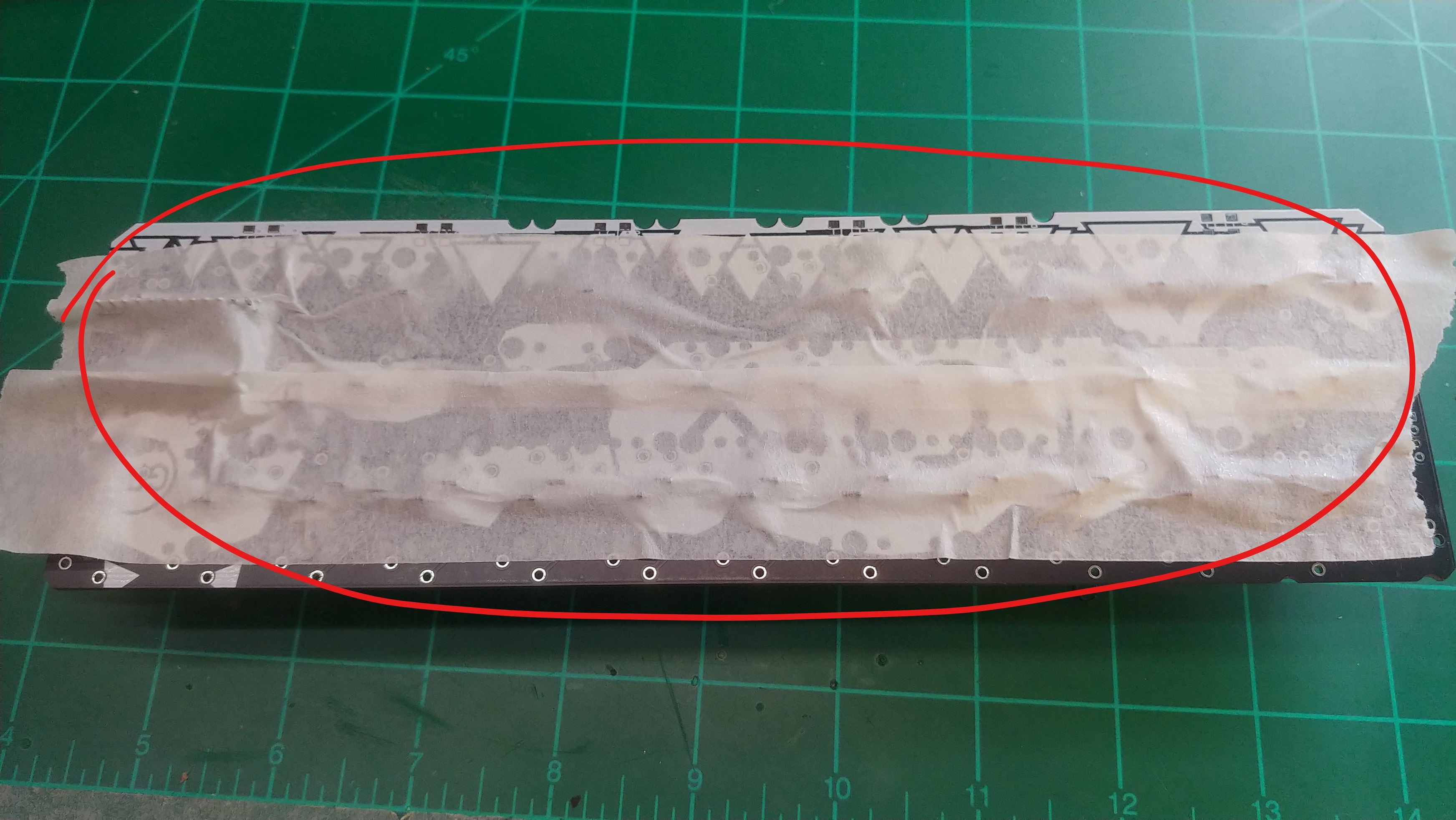
 The easiest way to install the diodes is to place them all in, then use masking
tape to hold them in place. Now you can flip the whole thing over, clip the legs
off, and solder them all in. I find it’s easier and looks cleaner if you clip
the legs before soldering, but you could also solder first.
The easiest way to install the diodes is to place them all in, then use masking
tape to hold them in place. Now you can flip the whole thing over, clip the legs
off, and solder them all in. I find it’s easier and looks cleaner if you clip
the legs before soldering, but you could also solder first.
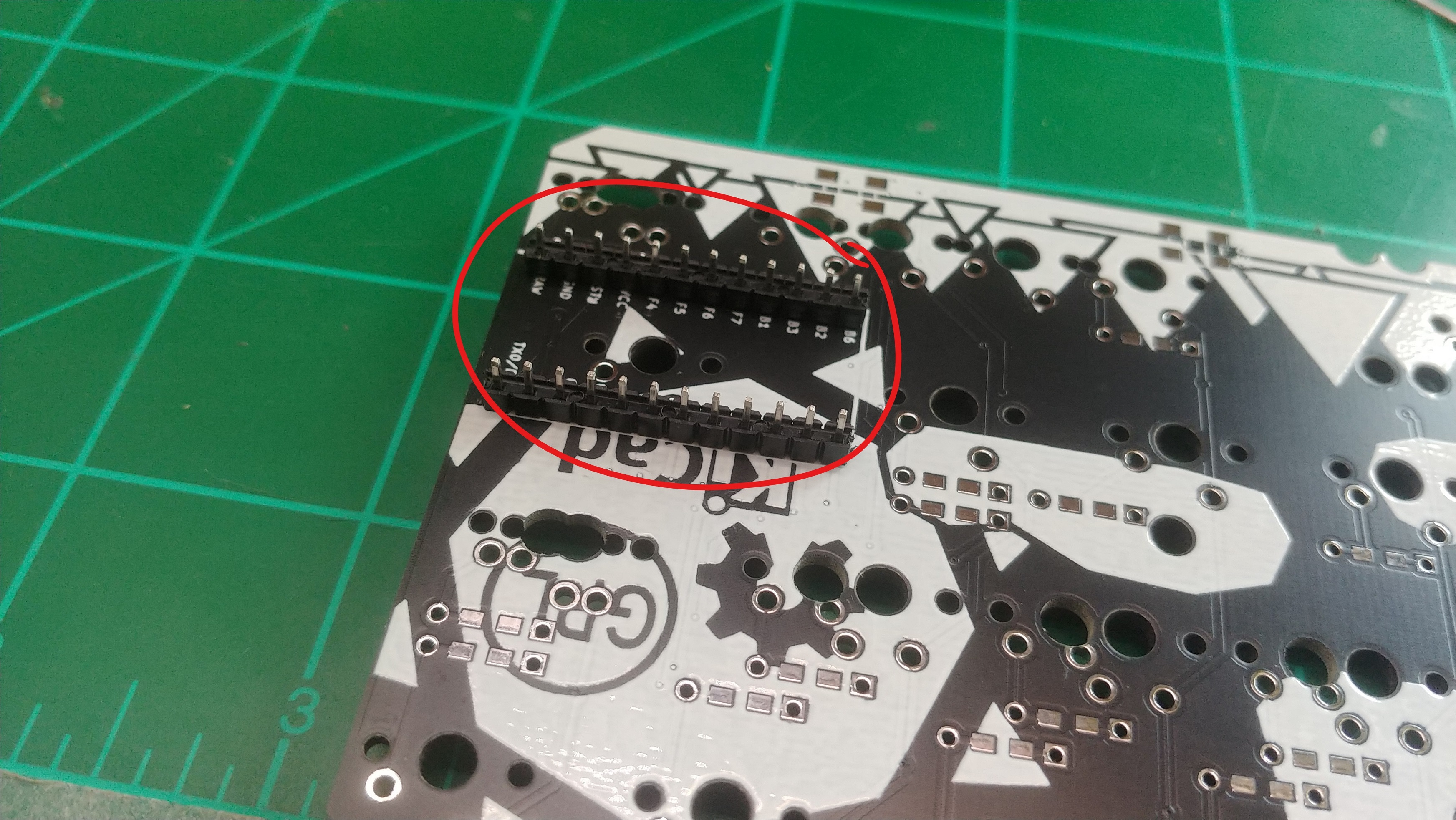
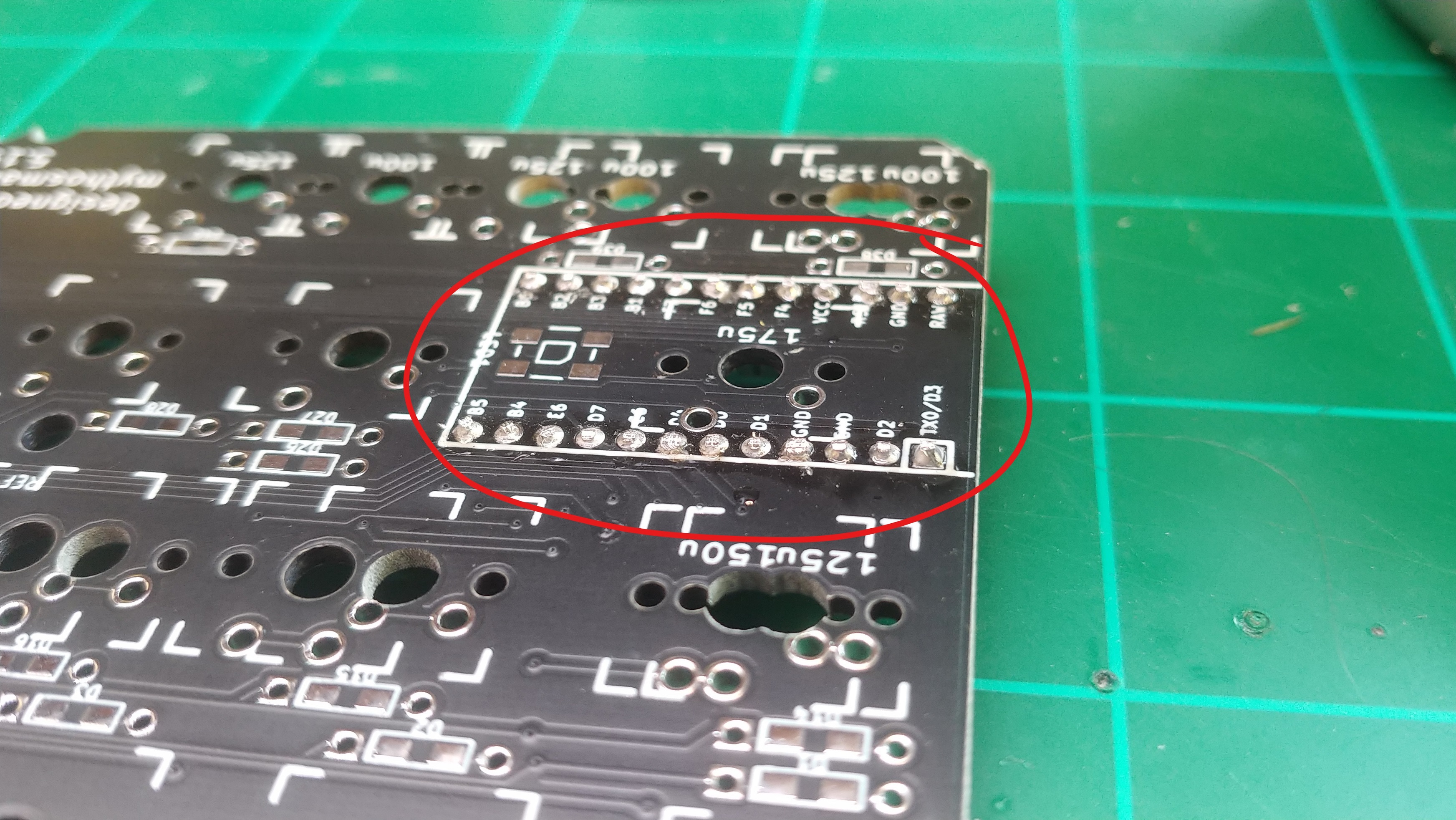
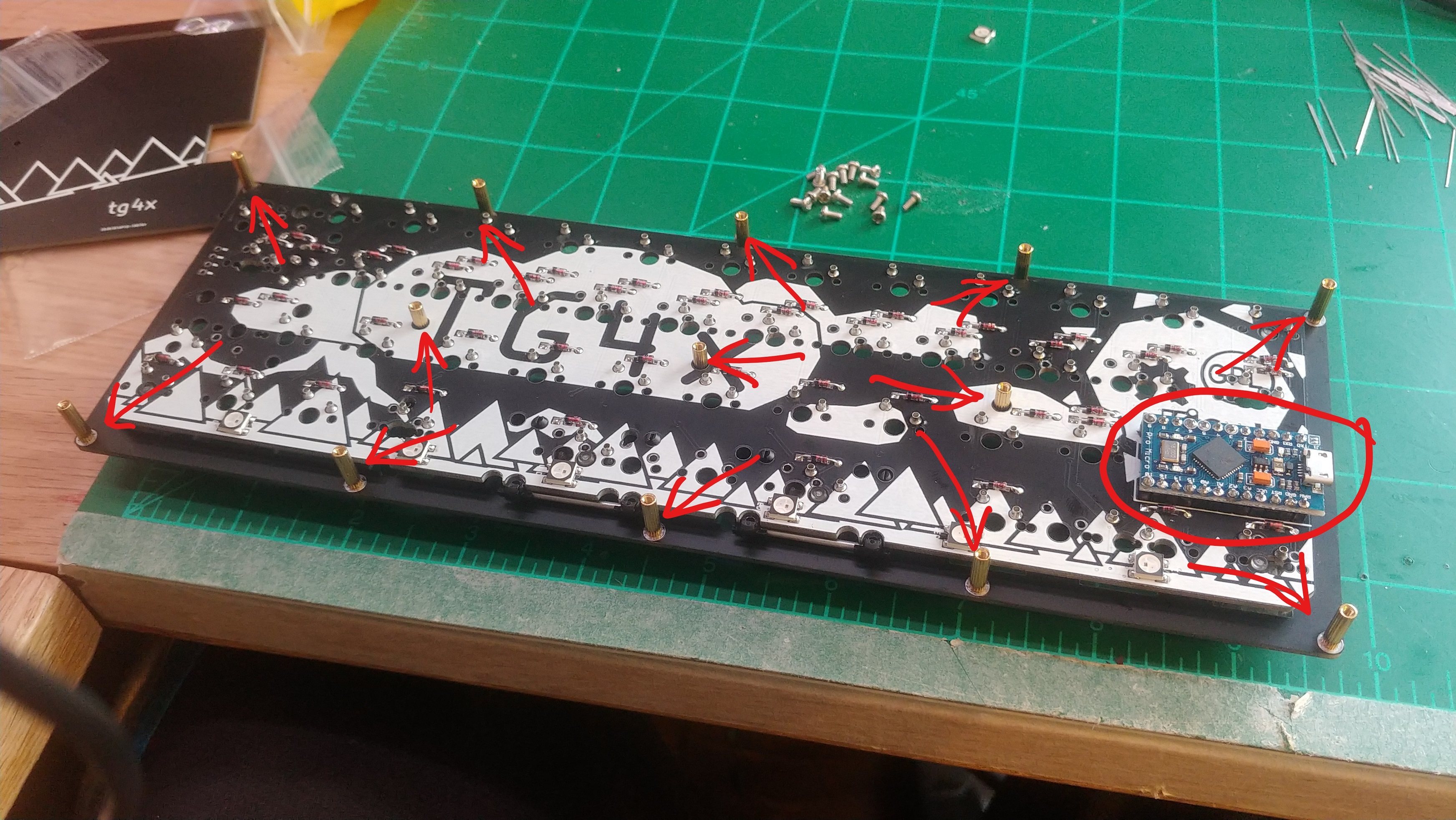
 Next, you want to solder in the headers for the pro micro. You want them on the
bottom of the pcb, which is the side with the big fancy graphic. Don’t solder
the pro micro on yet! If you do, it’s gonna be really hard to solder the
switches later. I’d put the short end of the headers away from the pcb, with the
long legs going through. Then clip them flush with pcb.
Next, you want to solder in the headers for the pro micro. You want them on the
bottom of the pcb, which is the side with the big fancy graphic. Don’t solder
the pro micro on yet! If you do, it’s gonna be really hard to solder the
switches later. I’d put the short end of the headers away from the pcb, with the
long legs going through. Then clip them flush with pcb.
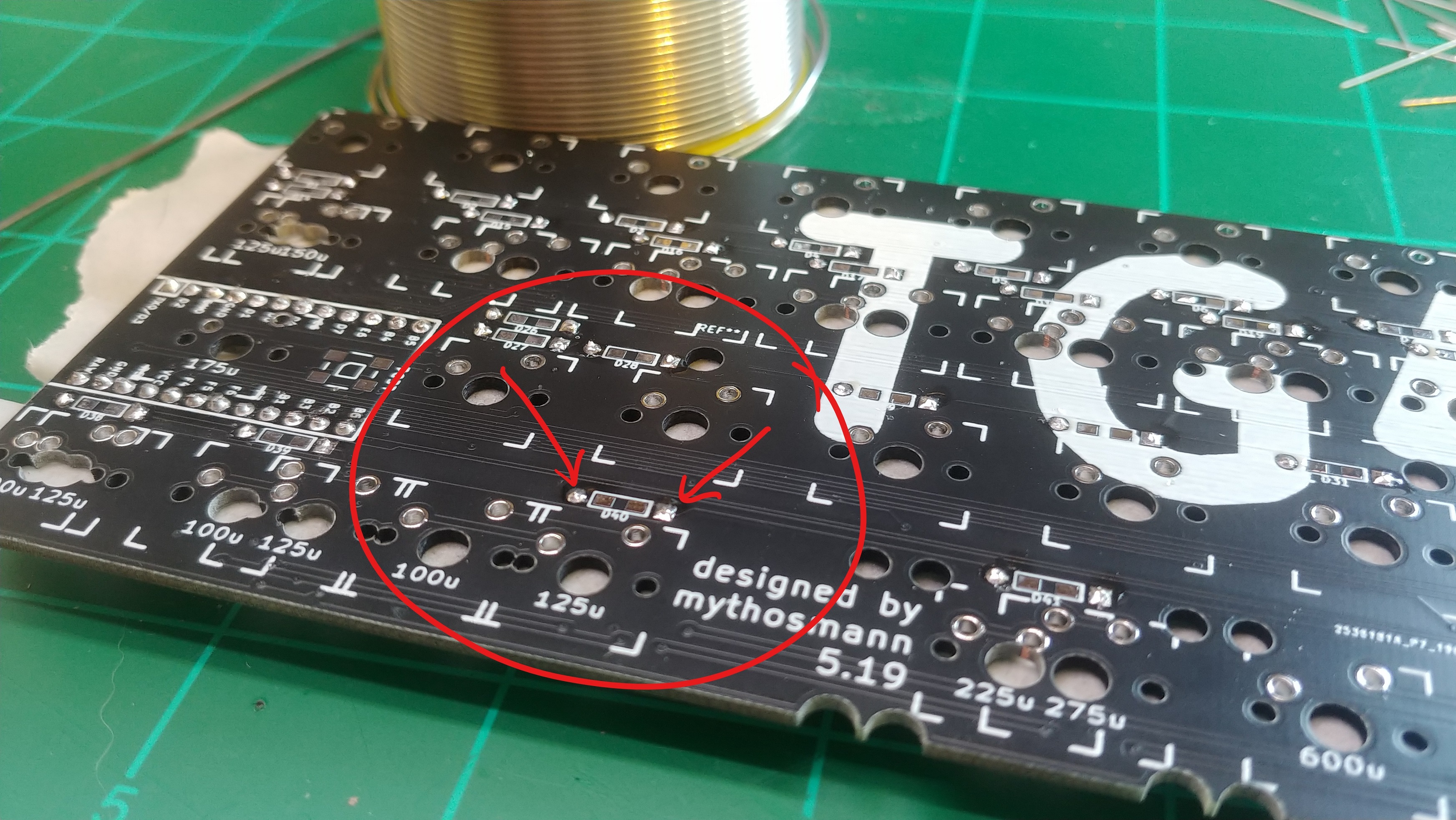
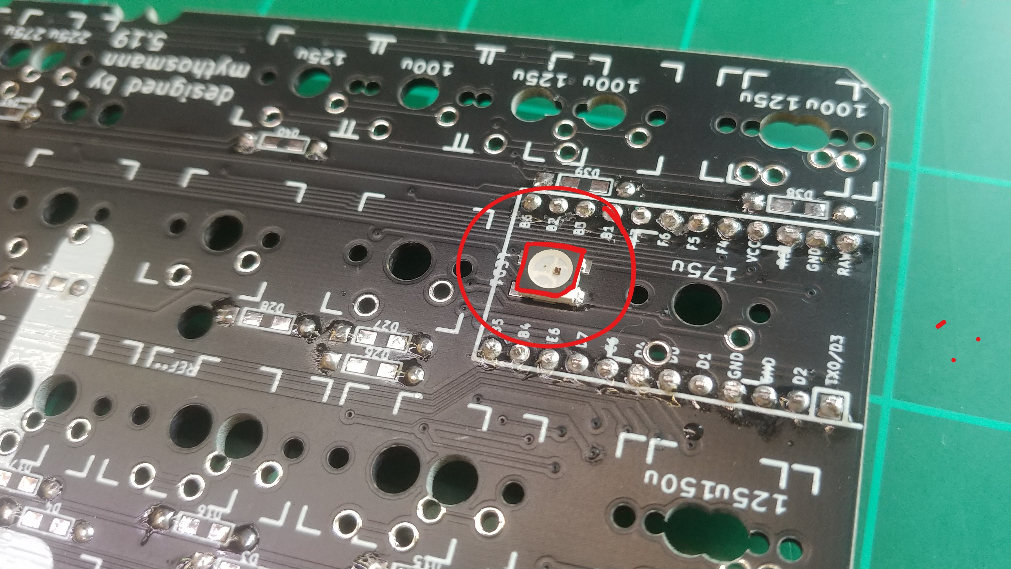
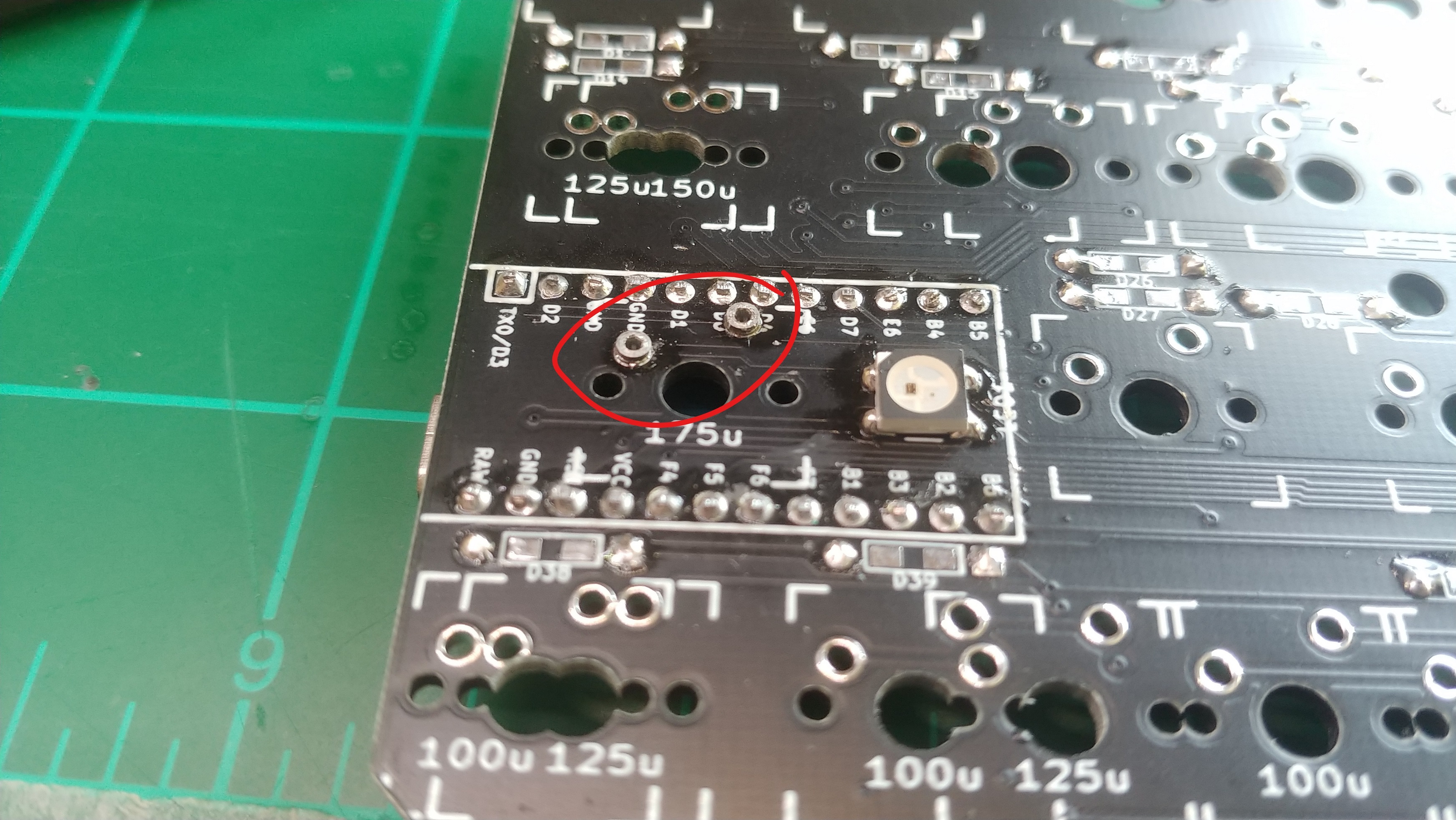
 Next, solder on the leds. There’s one on the top of the pcb, and six on the
bottom. For the one on top, you want to make sure that the white corner is
facing the left side of the pcb. The leds on the bottom of the pcb all face down
to the right, except for the one on the far right, which faces the other way.
Next, solder on the leds. There’s one on the top of the pcb, and six on the
bottom. For the one on top, you want to make sure that the white corner is
facing the left side of the pcb. The leds on the bottom of the pcb all face down
to the right, except for the one on the far right, which faces the other way.
 If you have mill-max sockets, you’ll want to solder them in now. I solder them
just like diodes, so I’ll put them all in, tape over them, then solder them from
the underside. If you don’t have the sockets, skip over this step.
If you have mill-max sockets, you’ll want to solder them in now. I solder them
just like diodes, so I’ll put them all in, tape over them, then solder them from
the underside. If you don’t have the sockets, skip over this step.
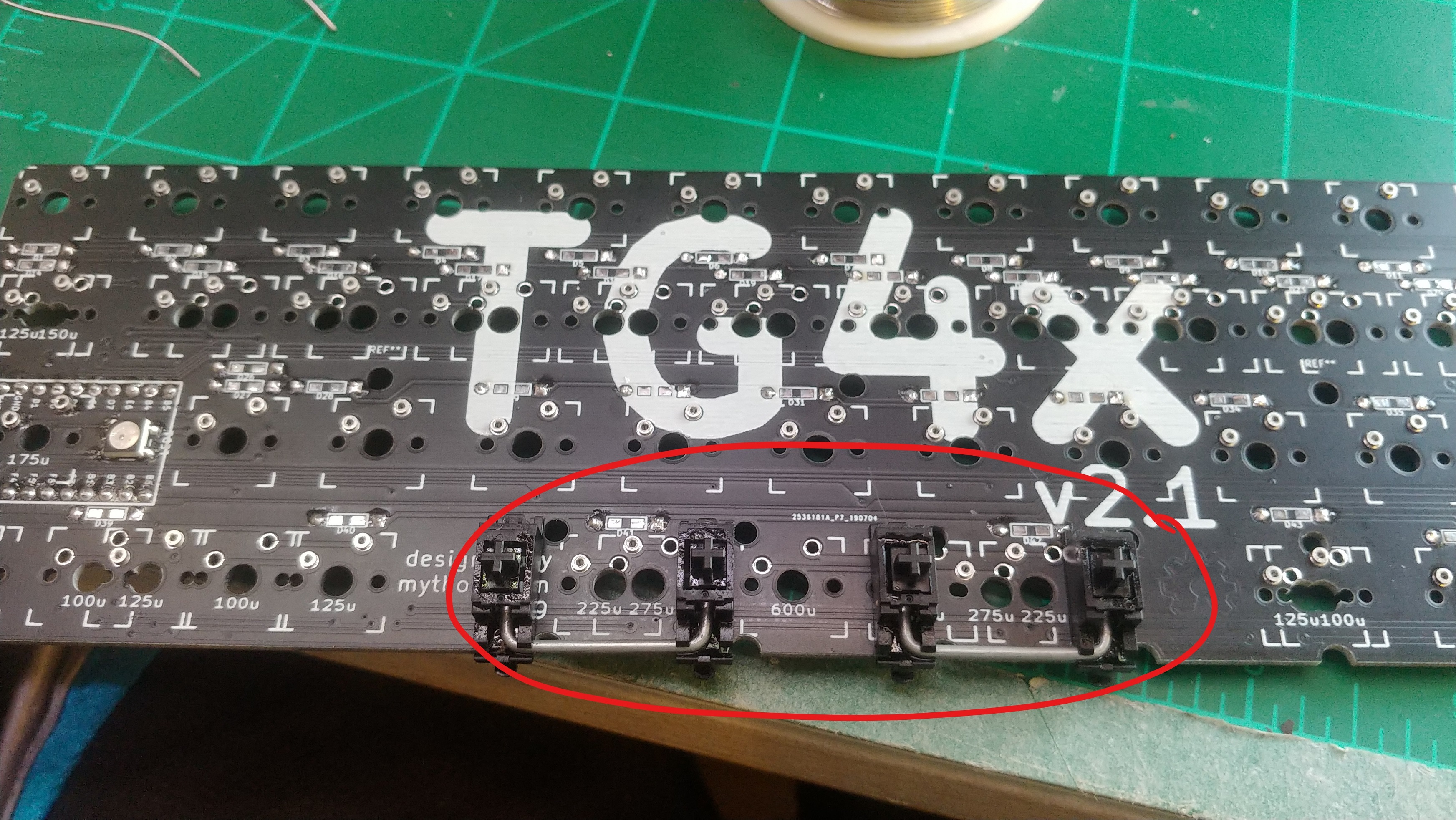
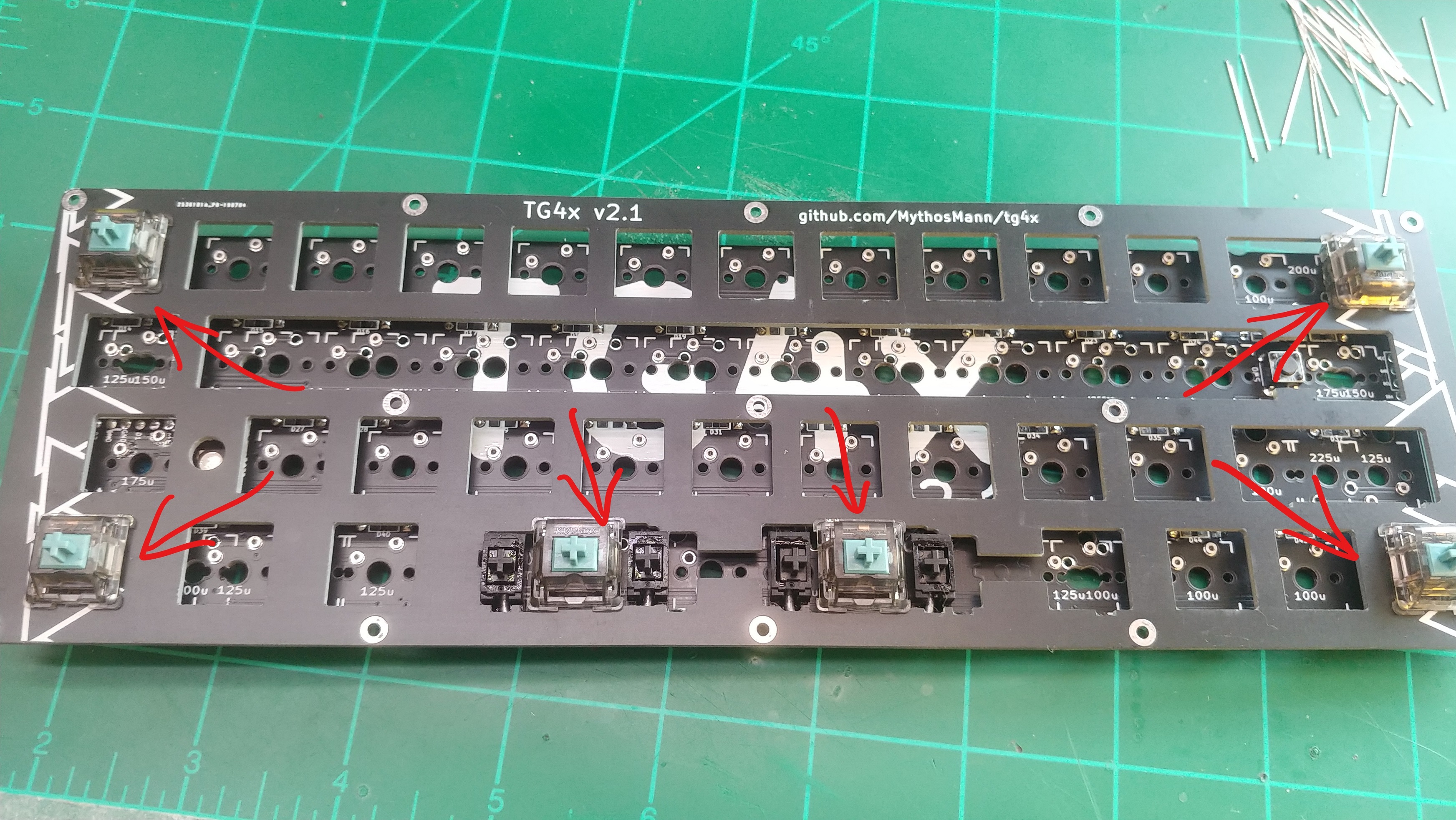
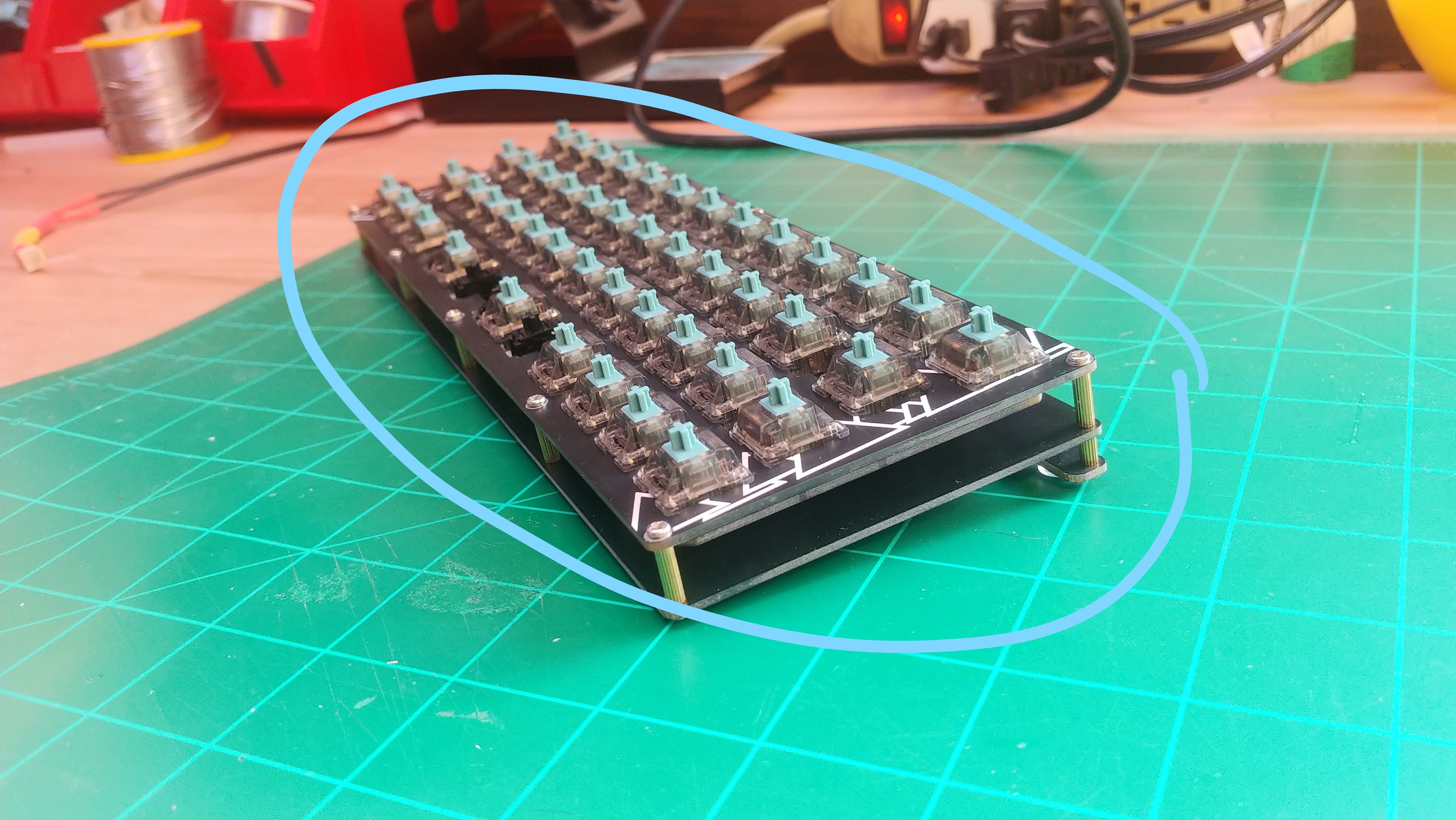
 Make sure you put the stabilizers in before you start to add the switches. Put
switches in each of the corners of the top plate, then fit it into the pcb. I
also like to put switches where the stabs are. Solder those switches into the
pcb. Now it’ll be easier to fit the rest of the switches in, and solder them. Of
course, if you’re using mill-max sockets, there’s no need to solder the
switches.
Make sure you put the stabilizers in before you start to add the switches. Put
switches in each of the corners of the top plate, then fit it into the pcb. I
also like to put switches where the stabs are. Solder those switches into the
pcb. Now it’ll be easier to fit the rest of the switches in, and solder them. Of
course, if you’re using mill-max sockets, there’s no need to solder the
switches.
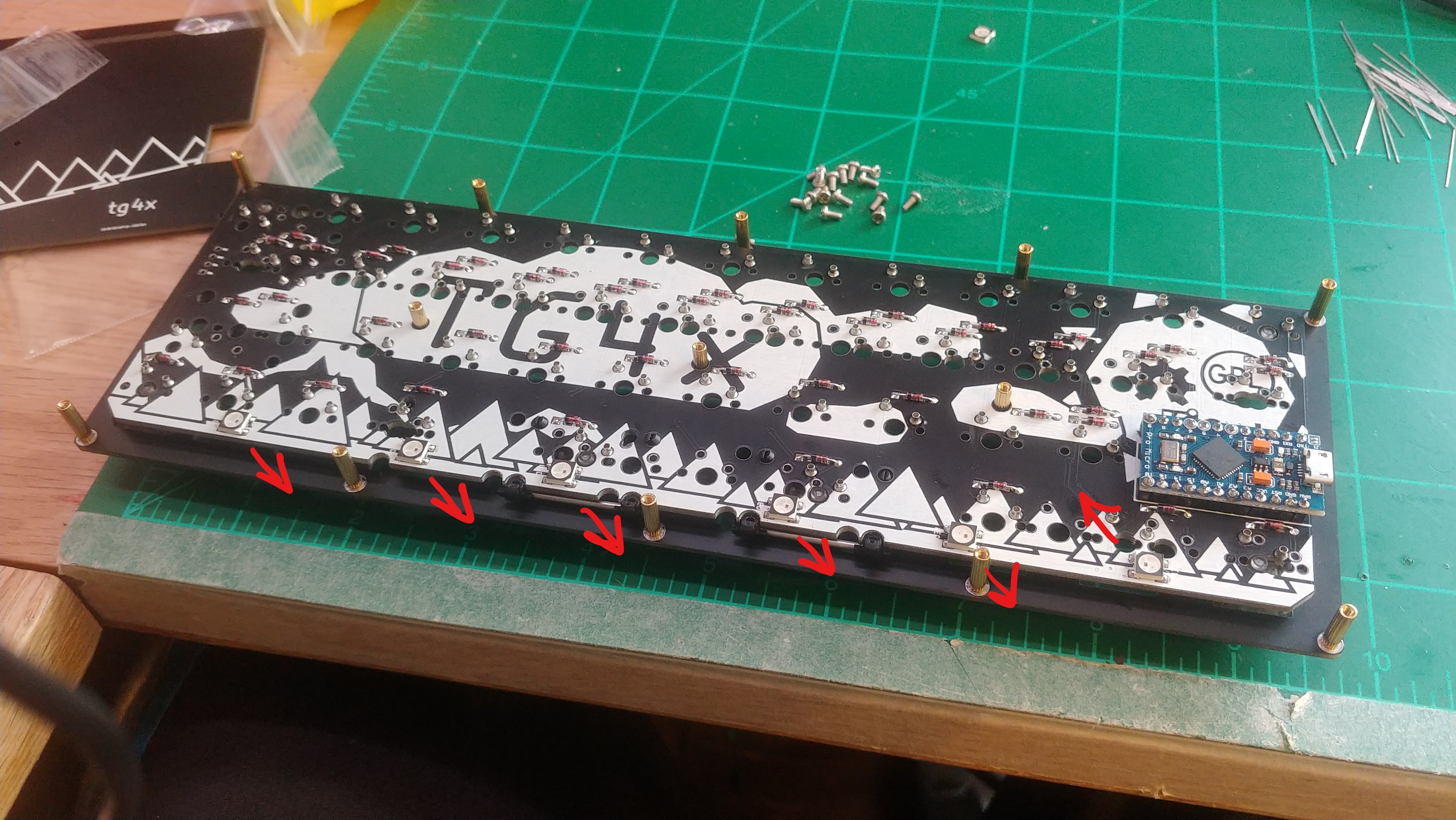
 After you’ve got all the switches installed, screw in all of the standoffs to
the top plate. There are 13 in total. Put the bottom plate on, and screw it
down.
After you’ve got all the switches installed, screw in all of the standoffs to
the top plate. There are 13 in total. Put the bottom plate on, and screw it
down.
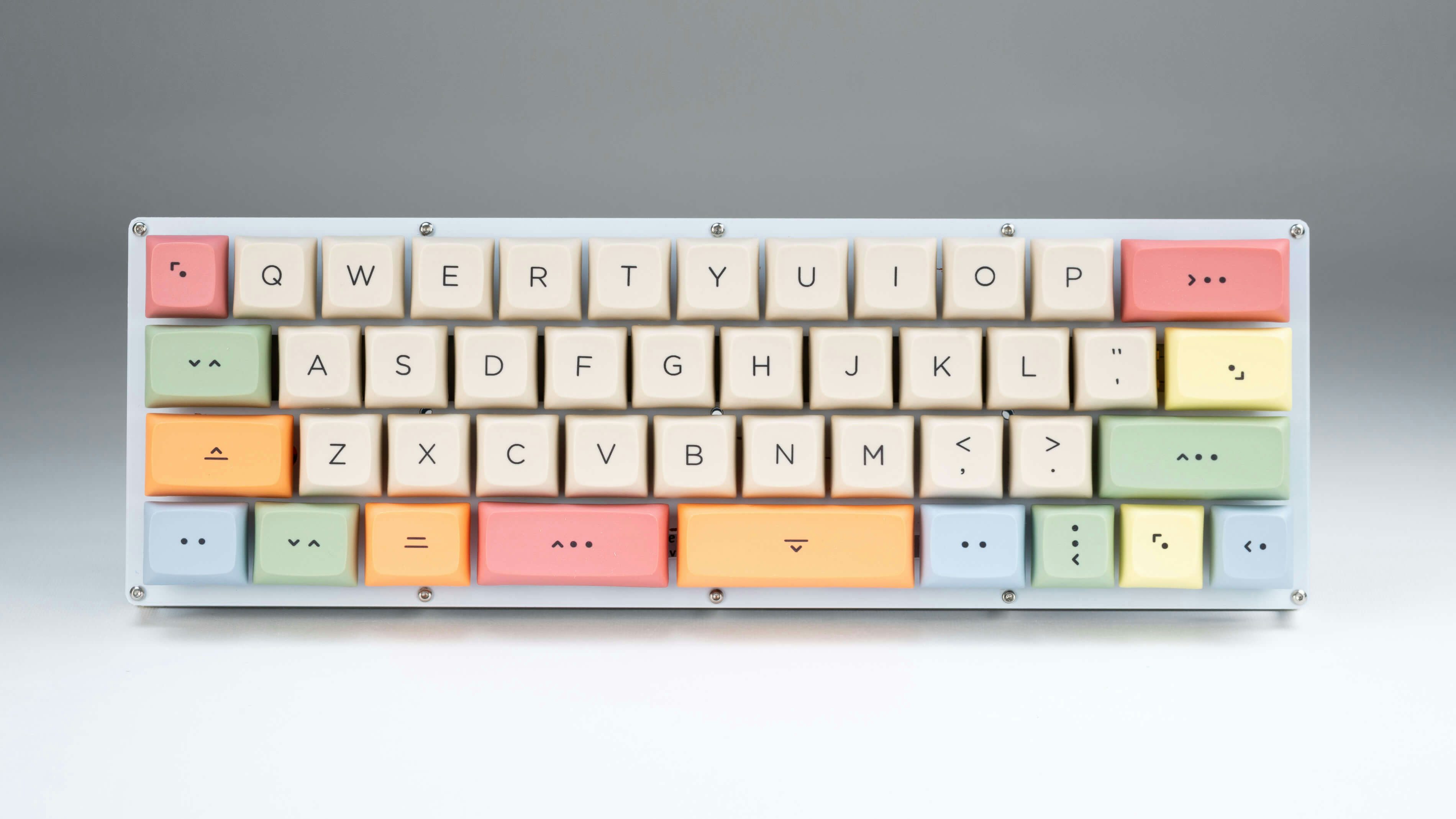
Now all you’ve got to do is stick on some rubber feet, and find your keycaps.
Firmware
QMK
In qmk this keyboard can be found under tg4x.
To begin, follow the QMK setup guide. (if working from an existing installation, an update may be needed.)
For flashing instructions, see doc or video
KMK / PEG
In Peg or KMK this keyboard can be found under tg4x
Peg can be downloaded here, and the quick start can be seen here.
For Kmk can be downloaded here and the quick start can be seen here
Extra
For questions, ask in Boardsource Discord server