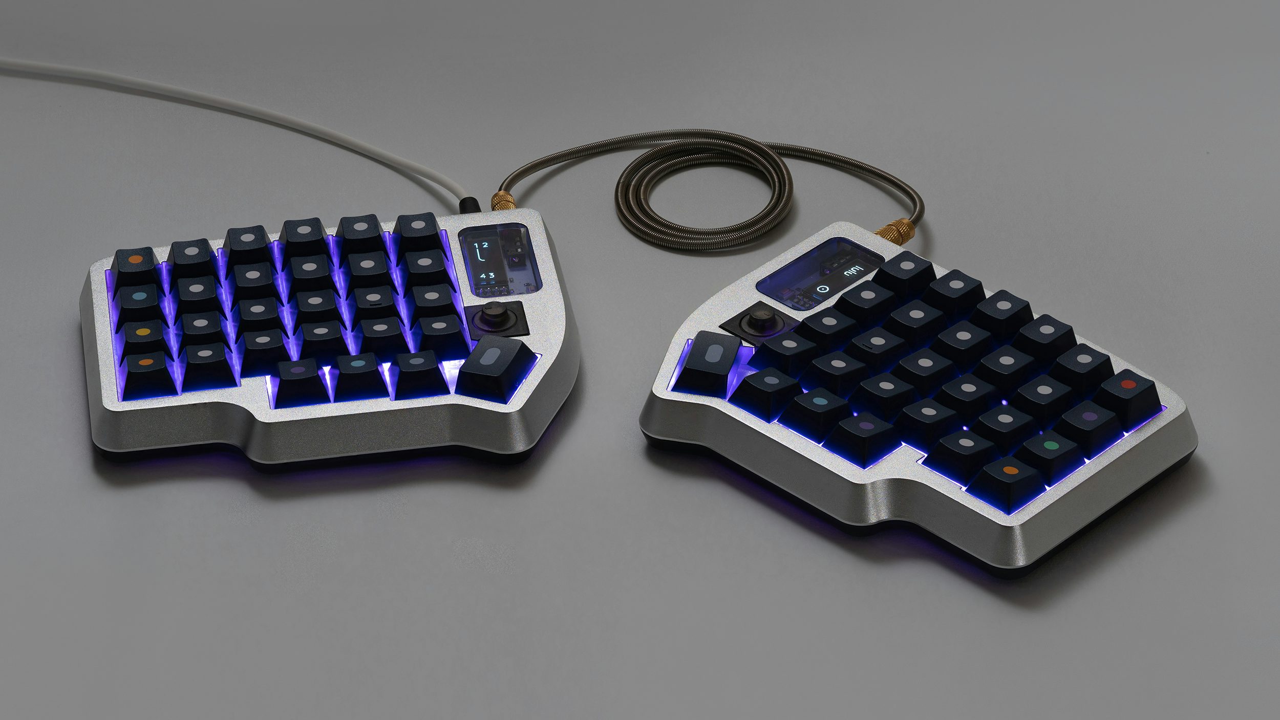
Welcome to the lulu build guide, here you will find a step by step guide on how to build your lulu as well as a list of items your kit(s) should contain. Please follow this guide in its entirety, if you have any questions or need more hands-on help you can enter the Discord and ask under the #build-help channel.
We recommend you do each step on both halves of the keyboard prior to moving on to the next step, but of course you can also complete a side and then do the next, the choice is yours.
IMPORTANT: When using a split keyboard, it is extremely important that you plug in the halves and then the board to your computer in the correct order. This is the correct order to follow:
Plugging In the Board: First connect the halves via TRRS, then plug the board into your computer via USB.
Unplugging The Board: Disconnect the board from your computer, then unplug the halves TRRS connection.
DO NOT PLUG/UNPLUG THE TRRS CABLE WHEN THE BOARD IS PLUGGED IN TO YOUR COMPUTER
Quick Links
Kit Contents
Case Kit
- 2x Aluminum Top Case
- 2x OLED Cover (Frosted)
- 2x OLED Cover (Clear)
- 2x Lower Polycarbonate Pieces
- 2x OLED Plug
- 8x M2 x 6mm Conical Flush Head Phillips Screw
- 8x M2 x 6mm Cap Head Bolt
- 1.5mm Allen (Hex) Key
lulu SMT PCB
- lulu SMT Hotswap PCB Note: Your PCB box is unsealed and the anti static bag is open because we had to re-flash some PCBs that did not have the bootloader written to them correctly.
Tenting Kit
- 2x 10° Tenting Legs
- 2x 15° Tenting Legs
- 2x 20° Tenting Legs
- 8x M2 x 4mm Conical Flush Head Phillips Screw
Encoder Kit
- 2x Encoder Plug
- 2x Encoder Knob
- 2x Rotary Encoder Components
Extra Lower Piece Kit
- 2x Polycarbonate Lower Pieces
Other Items Required - Not Included
- 58 MX Switches (or 56 if you’re using a Rotary Encoder Kit)
- P0 Phillips Screwdriver (P1 size also may work but is more likely to strip screws)
- For Encoder Kit Only:
- Soldering Iron
- Solder
If you’re missing a piece in a kit, please reach out to us at help@boardsource.xyz and we will get you the part sent out ASAP.
Install OLED Cover and Plug Into Aluminum Top Case
Required Parts In This Section:
- 2x aluminum top case
- 2x OLED cover (frosted or clear)
- 2x OLED plug
- 4x m2x6mm flat head bolt
From the backside of the top case (front laying down on a surface) insert the OLED Cover into the OLED window. Line up the cutouts on the OLED cover with the posts on the aluminum. You can apply a bit of force in order to fully seat it. When you think the cover is fully seated, inspect the cover from the front, the cover should be close to flush with the aluminum. If it seems to be inset too much, you likely installed the cover upside down.
Again from the back of the top case, inset the OLED Retention Plug into the case. There is only one correct orientation for this piece, simply align the cutouts on the piece with the posts on the aluminum and insert. Fasten the OLED retention plug to the top case with the conical flush head phillips screws in the Case Kit Box. Tighten the retention plug until it is flush with the aluminum. Do not over tighten the OLED Retention Plug or cracking may occur.
With the OLED Retention Plug properly installed and fastened, you can make small final adjustments by hand to the OLED Cover to ensure the final fit is flush with the aluminum on the top side. Slight movements will not cause any cracking and the cover should stay in place.
PRO TIP: Prior to moving on, clean the OLED Cover to remove any smudges or marks you made during installation. The clear OLED Cover is easily scratched, we recommended using a glasses cleaning cloth/microfiber cloth, do not apply too much pressure when cleaning. The underside will be hard to get to later, so it’s best to clean it now.
Install Encoder Plug
NOTE: This section is only applicable if you purchased a Rotary Encoder Kit, if you did not then simply move on to the next step.
Required Parts In This Section:
- 2x Aluminum Top Case
- 2x Encoder Plug
Now we are going to insert the Encoder Plugs into the Aluminum Top Case. It is important to differentiate the left plug from the right plug, as they are not the same. Forcing the incorrect plug into the wrong side may cause damage to the plug.
If you inspect the Encoder Plugs closely, you will notice each plug has 3 corners that are 90° corners, and one is a bit weird with an angle. That angle is meant to match the ‘pointy bit’ of aluminum that sits above the thumb key on each half of the lulu. Additionally, if you inspect the sidewalls of the Encoder Plug you will notice one has a small cutout towards the bottom. This cutout helps with removal of this plug in the future. On each half, that cutout is supposed to face towards the keys. In other words, the left plug’s cutout faces left, and the right plug’s cutout faces right when installed properly.
Let’s check which plug is which by confirming where the ‘weird angled corner’ lines up when you orient the cutout correct. When oriented properly, the left half’s Encoder Plug will have its weird corner in the bottom left, and when the cutout on the right Encoder Plug is oriented correct it will have its weird corner in the bottom right.
When in doubt, sit back, take a deep breath, and imagine how this piece would look if you inserted it into the key switch location. The weird corner’s angle should CONTINUE the angle of the pointy aluminum, not interfere or intersect with it. I am sorry this is semi difficult to explain, we will add some pictures in the future.
Now that you’re (hopefully) sure which half the Encoder Plug belongs to figured out, we can start inserting them into the key switch location. Make sure the key switch location is clear of any debris prior to installation or it will cause the plug to sit proud of the aluminum.
Place the Encoder Plug into the key switch location and let it rest. Check to make sure it’s aligned properly by looking straight down on it, and try to ensure the top of the plug is laying flat, not at an angle. With even force apply downward pressure onto the plug, it should click into place. If you aren’t able to seat the plug, one of two things are happening, either you aren’t applying enough force, or you’re using the wrong side’s plug. Before attempting installation again, double check the orientation of the plug, realign it, and apply even downward pressure again. This takes a bit of force, but gets easier after use if you remove/re-insert it over time.
When installed properly the Encoder Plug should sit flush with the aluminum. If it does not sit flush, you can try applying a bit more force. If issues persist, remove the encoder plug and inspect the plug and surrounding areas for any debris.
Solder Encoder to PCB
NOTE: This section is only applicable if you purchased a Rotary Encoder Kit, if you did not then simply move on to the next step.
Required Parts In This Section:
- 2x Rotary Encoders
- 1x lulu PCB or Lily58 PCB with rotary encoder support
- Soldering Iron
- Solder
Prior to installing the Rotary Encoder onto the PCB, check to make sure each of the connection legs on the encoder are straight. They are fairly easy to bend and this causes issues during installation. Simply straighten each leg out to help with easy installation.
The rotary encoder can only be placed onto the PCB in one orientation, make sure to match up the number of legs with the number of holes on the PCB. The 3 pins should point down towards the thumb clusters. Insert the rotary encoder into the PCB and make sure that it is fully seated and resting on the PCB flat. Improper/uneven installation will cause fitment issues elsewhere.
With the rotary encoder properly installed on the PCB, flip the PCB over and solder the 5 connection leads, and then solder the 2 retention legs. It is smart to periodically flip the PCB over to confirm the encoder is fully seated onto the PCB and resting on it and did not raise or move at all. Be careful not to heat the pads near the hot swap socket too much, and you do not need to apply an abundance of solder. Nothing bad will happen if you burn the hot swap socket, but it may cause a bit of an ugly mark. It is very possible to solder all leads without disturbing the hot swap socket.
Install OLED-S
Note: This section is only applicable if you purchased OLED-S with your lulu, if not move on to the next step.
Unpackage the OLED-S from the anti-static bag it comes in. Install OLED-S into the 4 header pin sockets (in one strip) on the front of the PCB below the microcontroller. Simply align the posts on the OLED-S with the header piin sockets, and apply downward pressure. When fully inserted into the sockets, you can bend the pins slightly if you need to make it more level.
Insert Alignment Switches Into Plate
Required Parts In This Section:
- 2x Aluminum Top Case
- ~8x Switches of Your Choice
To help connect the PCB to the plate/switches, it helps to put a few switches through the plate first. This allows you to have a few switches per half help hold up the PCB. Simply insert 4-6 switches per half, trying to get them in all four corners and not all in the same spot. If you’re looking at the top case with the number row facing up, the switch legs too should face ‘up.’ Take a look at the PCB, imagine how the switches go into the hot swap sockets in the next step, and confirm you’re orienting the switches into the plate properly.
Connect PCB to Switches and Plate
Required Parts In This Section:
- 2x Aluminum Top Case
- 2x PCB Halves
- Plate Foam (Optional)
If you have not snapped away the permitter pieces on your PCBs yet, do so at this time. You can simply use your hands and snap them off, pliers can help a bit if small remnants are left behind. The PCBs must be totally separated from one another for this to work.
Lay your top case (with alignment switches installed) face down onto the table. You should not see the colored switch stem, that’s against the table. You should see the legs of the switches from this view.
NOTE: If you’re using plate foam, you’re going to need to install that now. When the top case upside down, insert it into the top case in the proper orientation. You should see it align perfectly with the curves of the case and the switch holes.
Now you may place the PCB for that half on top of the alignment switches, doing your best to align the hot swap sockets with the switch legs. You can sometimes feel it ‘drop’ a TINY bit into place, this means you aligned it well and the switch legs are ready to be inserted into the hot swap sockets. Press down on each hot swap socket that has an alignment switch inserted. You should be able to feel the PCB push down and see the ends of the switch legs through the hot swap socket. Do this for each alignment switch.
When each alignment switch is properly inserted into the top case, and each hot swap socket is properly seated, you should be able to pick up the assembly and it won’t drop or fall. The PCB, switches, plate, and top case are now all connected via these alignment switches. You can press them all together once more to ensure proper installation. If one does not seat properly or something isn’t looking quite right, make sure the switch is oriented properly, there are four possible directions a switch can be inserted, and only one is correct to line up with the holes in the hot swap socket. Even if inserted properly, it is also possible the switch legs are bent, this will also cause the switch to not seat properly. Do not use too much pressure or force anything when performing this step. A reasonable amount of force can be used to seat the switches into the hot swap socket, but if you’re forcing anything or pressing too hard it means something is wrong, and you run the risk of popping a hot swap socket off the PCB.
Install Knob Onto Rotary Encoder
NOTE: This section is only applicable if you purchased a Rotary Encoder Kit, if you did not then simply move on to the next step.
Required Parts In This Section:
- 2x Encoder Knob
With the PCB attached to the top case assembly via switches, if you have a rotary encoder installed on your PCB you should now see the stem from the top side through the Encoder Plug. If this doesn’t seem to fit, ensure your rotary encoder is properly seated against the PCB and is completely flat.
Simply insert the Rotary Encoder Knob onto the Rotary Encoder Stem. The Knob can only be placed onto the stem in a single direction, check to ensure proper alignment prior to applying pressure. The steam has a single flat side, and the interior of the knob has a single flat side. Line them up and then apply downward force. This takes some pressure and is a friction fit, support the PCB from the back when installing the Knob to make sure you don’t push the PCB away from the switches and cause them to disconnect.
You will likely hear a click, that is okay it is the ‘press down’ function of the rotary encoder and makes a clicking noise, nothing broke. Use a bit of pressure even past that click and fully seat the knob onto the stem. You should not have to use an extreme amount of pressure or force the knob onto the stem. If you feel like it isn’t going onto the stem, pleasure confirm the proper orientation of the knob by aligned the flat surfaces. Forcing the knob onto the stem in the wrong orientation can crack the knob.
Insert Remainder of Switches
Now, you can go through the remainder of the of the switches and insert them into the assembly from the front. Remember, there is only one way a switch can be inserted properly, so double check the orientation prior to installation and also confirm the switch legs are straight. SUPPORT EACH HOT SWAP SOCKET FROM THE BACK WHEN INSERTING SWITCHES. I use my fingers to support the hot swap from the back while I press the switch in from the front and go one by one. If you do not support hot swap sockets from the back during switch installation, it is possible they will pop off the PCB causing permanent damage. Ensure each switch is fully seated into the plate and hotswap socket.
Install Tenting Legs
NOTE: This section is only applicable if you purchased a Tenting Kit, if you did not then simply move on to the next step.
Required Parts In This Section:
- 2x PC Lower Pieces
- 2x Tenting Legs in the angle of your choice
- 4x M2 x 4mm Conical Flush Head Phillips Screw
Take a single screw and place it into the appropriate hole on the interior of the lower piece. Using three hands, hold that screw in place with your screwdriver while you properly align the tenting leg with the screw from the other side. Tighten the screw to fasten the tenting leg to the lower piece. Insert the other screw and attach the other side of the tenting leg to the lower bottom piece.
Do not over tighten screws, if you try to lock these down with an immense amount of force, it is possible to unset the threaded insert in the tenting leg. However, it is totally fine to tighten them enough where you ensure there is zero movement or wobble in the tenting leg. When properly tightened the tenting leg should not move at all.
Finale Keyboard Assembly
Required Parts In This Section:
- 2x PC Bottom Pieces with Tenting Legs Installed (If Applicable)
- 2x Aluminum Top Case with PCB, Switches, OLED, OLED Covers, and OLED Plugs Installed
- 8x M2x6mm Cap Head Bolt
- 1.5mm Allen (Hex) Key
Lay the Aluminum Top Case upside down on a surface (resting on the switches) then align the polycarbonate lower piece on top of it. The pieces should align themselves and you will see the threaded posts through the holes on the lower piece. Connect the pieces together using the Hex Cap Head Bolts, 4 per half. Do not over tighten these bolts, as too much pressure may cause gaps. Just snug them up and everything should be secure and aligned properly.
Enjoy your keyboard
Install some keycaps and post up a picture on Reddit/discord/Instagram and tag us. We hope you enjoy your keyboard if you have any questions we have a build help section in our discord hop in and there are loads of helpful people in there at all hours of the day ready to help.
Firmware
QMK
In qmk this keyboard can be found under boardsource/lulu/rp2040. To begin, follow the QMK setup guide. (if working from an existing installation, an update may be needed.) \ For flashing instructions, see doc or video
KMK / PEG
In Peg or KMK this keyboard can be found under lily58 or boardsource-lulu-blok in Peg
Peg can be downloaded here, and the quick start can be seen here.
For Kmk can be downloaded here and the quick start can be seen here
Here are some links to other articles that may help you get the most out of your new keyboard:
- Get the most out of your PCB Unleashing the High-Tech Power of Custom Keyboards
- Keyboard Programing
Extra
For questions, ask in Boardsource Discord server