lulu Flashing Guide

lulu Flashing Guide

Written By: Boardsource

Category: guides - easy

Tags: qmk, kmk, flashing

Flashing Your lulu PCB

Quick Links

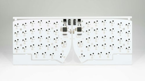
This page is meant to be a reference to flashing your lulu SMT PCB.

Please note that updating and making edits to your keymap is not covered here, but the lulu is designed to work out of the box with Peg. Click here to learn more about Peg and download.

Please follow this guide in it's entirety, but if you feel you need additional help, feel free to enter our Discord server and ask for help under in the #hardware-help channel.

Flashing With Defaults

While using Peg, you do not need to use the Boot switch or Reset switch. If for some reason you need to get your PCB back to a known working state or ‘Factory Reset’ it, you can flash the PCB with the default Peg map.

The files below come with everything you need, BS-Python (CircuitPython Fork), KMK, all required libs, and the default lulu keymap.

Flashing With VIA

Below you will find the VIA Map available for download. Download the VIA Map and continue with the guide as normal.

  • Coming Soon

Flashing Process

First, unplug your lulu PCB from the computer.

On the back of your PCB you will notice a sliding switch around where the controller would sit on the other side. This switch has two states, Default and Boot. When you open your PCB, the switch should be in the default position. The switch’s default position is outlined with silkscreen.

In order to put the PCB into boot mode, you must (while the PCB is unplugged) put the switch into Boot mode. When the switch is in Boot mode you will notice the silkscreen outline indicating it’s Default position.

Check the diagrams below to see these two states, Default and Boot.

Default Boot Switch State

boot switch

Boot Mode Switch State

boot switch

With the PCB in Boot mode, you can plug it back into your computer.

After a few moments, your PCB should appear as a Drive on your computer named "RPI-RP2.” After you locate this drive, before doing anything else, put your PCB back into Default mode. The drive will NOT disappear.

With the Drive "RPI-RP2" located on your computer AND the Switch reset to it’s Default position you can drag and drop the Uf2 files onto the drive (onto the PCB). When it is done transferring the file, your PCB will reboot. Because you put the switch back to it’s Default position, when the board restarts it will no longer be in Boot mode and will be good to go.

If you’ve successfully transferred the Uf2 file, you should see the LEDs turn back on, and a new ‘BSPYTHON’ drive mount to your computer. If the transfer fails for any reason, simply repeat the steps, starting back from the beginning with the PCB unplugged from your computer.v